


NOL Compact Modulating
Page 16
Control Program Under Fault Conditions
And Lockout Indication
In the event of fault conditions the sequence
switch stops and simultaneously the lockout indi
cator. The symbol appearing above the reading
mark indicates the kind of fault encountered.
No start,
because, e.g., the CLOSE signal has
not been supplied to control box terminal 8
by the servo motor limit or auxillary switch,
or a contact has not been closed between
control box terminals 12 and 4 or 4 and 5.
Shut down of start up sequence,
because
the OPEN signal has not been supplied to
control box terminal 8 by the servo motor
limit switch. Terminals 6,7 and 15 remain
under voltage until the fault is corrected.
Lockout
due to a fault in the flame supervi
sion circuit.
Shut down of start up sequence,
because
the signal for the low flame position has not
been supplied to control box terminal 8 by
the servo motor auxillary switch. Terminals
6,7 and 15 remain under voltage until the
fault is corrected.
Lockout,
because no flame signal has been
received on completion of the safety time.
Lockout,
because the flame signal has been
lost during burner operation or an air pres
sure failure has occured.
Lockout on completion or after completion
of the control program sequence
due to ex
traneous light (e.g. flame not extinguished,
leaking fuel valves) or due to a faulty flame
signal (e.g. fault in the flame supervision cir
cuit or similar).
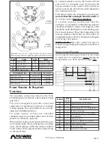
a - b
Start up sequence.
b - b
idle steps up to the self shut down of
the sequence switch.
b(b) - a
Post purge sequence.
When lockout occurs, the control can be reset
immediately. After the resetting (and also after the
correction of a fault which resulted in a controlled
shut down, or after each mains failure) the se
quence switch always runs through to the start
position, whereby
only
terminals 7,9,10 and 11
receive voltage in accordance with the control pro
gram. It is only then that the control unit programs
a fresh burner start up.
Note:
Do not press the lockout reset button (or
remote reset switch) for more than 10 seconds.
RWF40 M
ODULATING
C
ONTROL
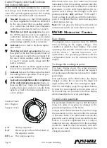
Basic display
The diagram below opposite shows the RWF40
after switching on the supply voltage. This
condition is called the basic display. The actual
operating value and the currently active set point
will be shown. Manual operation, self
optimization, the operating parameter and the
configuration levels can be activated from this
display.
To change the working set point.
The basic display shows the actual pressure/
temperature of the boiler in red and the required
set point pressure/temperature beneath in smaller
green digits.
One quick press of the PGM button, the display
changes to show the set point as the larger red
digits and the SPI in the lower small green digits.
Alter the red display using the up/down buttons
to show the new required set point, press exit or
let the unit time out to return to the basic display
which should be the new set point figure.
To enter a new parameter
The parameters dictate the way in which the burner
firing rate alters in response to changes in the
pressure/temperature of the boiler.
A major factor that determines the need to change
the parameters is if the burner is fitted to a steam
or hot water boiler. The table below indicates the
parameter and its setting for steam and hot water
boilers. It must be emphasised that it is only an
indication and any departure from these settings
should be made in small increments, with time
given to see how the burner is reacting to the
changed parameter.
1
a
b
b
1
Landis & Staefa
LAL1. Program
Sequence Disk.
I


