NDFL100-38 / BR003211 / Rev. 220900A
Page 22
One quick press of the PGM button, the display
changes to show the set point as the larger red
digits and the SPI in the lower small green digits.
Alter the red display using the up/down buttons to
show the new required set point, press exit or let
the unit time out to return to the basic display
which should be the new set point figure.
To enter a new parameter
The parameters dictate the way in which the burner
firing rate alters in response to changes in the
pressure/temperature of the boiler.
A major factor that determines the need to change
the parameters is if the burner is fitted to a steam
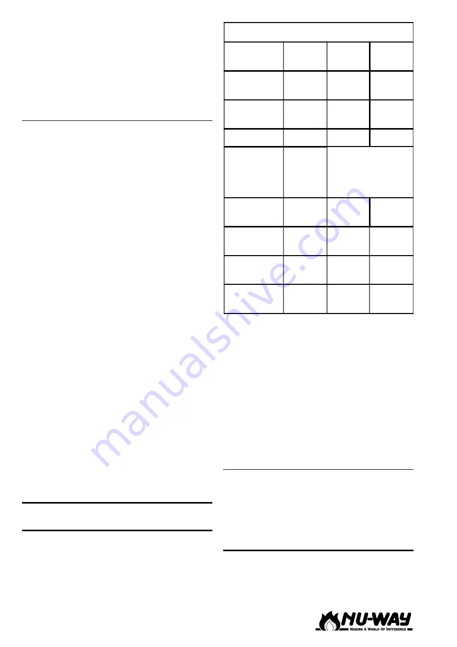
or hot water boiler. The table below indicates the
parameter and its setting for steam and hot water
boilers. It must be emphasised that it is only an
indication and any departure from these settings
should be made in small increments, with time
given to see how the burner is reacting to the
changed parameter.
Press and hold the PGM button down until the
green set point figure changes to an AL, the larger
upper figures show the value. Use the up/down
buttons to set the new value, press the PGM button
to enter the value and change to the next screen.
To cancel an entry press exit. Scroll through the
screens, (PGM button) modifying any value found
to be in error (up/down buttons). At the last screen
the PGM button will return the controller to the
original operating display.
At any point in the procedure the original operating
display can be obtained by letting the unit time
out, the value in the display at the time out will be
accepted.
A value can only be altered within the permitted
range of that parameter. All other parametrs must
remain as supplied.
Note: The detector range parameters SCL & SCH
are given as °C for Hot Water (temperature) and
bar for Steam (pressure).
NDFL - O
IL
O
PERATION
There are three atomising nozzles. The top nozzle
only sprays on low flame whilst two spray together
for the intermediate flame and all nozzles spray
on high flame. The oil operating pressure is 300
psi.
5:)
5
(&200(1'('
6
(77,1*6
3DUDPHWHU
'LVSOD\
+RW
:DWHU
6WHDP
3URSRUWLRQDO
EDQG
3E
'HULYDWLYH
WLPH
'W
5HVHWWLPH
5W
$FWXDWRU
WLPH
7W
6HWWRWKH$LU
'DPSHUUXQQLQJ
WLPHEHWZHHQORZ
KLJKIODPH
6ZLWFKRQ
WKUHVKROG
+\V
8SSHURII
WKUHVKROG
+\VW
'HWHFWRU
UDQJHVWDUW
6&/
'HWHFWRU
UDQJHHQG
6&+
At the start of the firing cycle, there is a pre-purge
with forced air and ignition. At the end of this
period, the air damper moves from the high fire
position to the ignition position. After a delay, the
low flame and safety (if fitted) solenoid valves are
energised, allowing oil to flow. The burner will light,
and the ignition is switched off. After a stabilising
period, the air damper moves to the low fire
position. If the flame fails to establish the burner
will go to lockout. If there is flame failure during
operation, the burner will shut down, and a single
restart cycle will follow.
Three-Nozzle System
When the air damper moves to the next pre-set
positions, the nozzle control valves open in
sequence. The burner will be held in any of the
three positions under the control of the boiler
thermostats.
C
OMMISSIONING
THE
B
URNER
Check that the electrical wiring is complete and
complies with all applicable Codes and Standards.
Check that the fuses are fitted and correctly sized.
Содержание NDFL100-38
Страница 34: ...NDFL100 38 BR003211 Rev 220900A Page 34 NOTES...
Страница 35: ...Page 35 NDFL100 38 BR003211 Rev 220900A...


