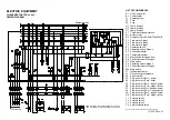
Nu-Way MOL 1650-3R B70 2-3 Скачать руководство пользователя страница 8

ELECTRIC EQUIPMENT

OIL BURNER CONTROL: LAL1...
WIRING DIAGRAM

LIST OF COMPONENTS
A1

Oil burner control

B1

Photoresistor

F1

Operating fuse

F2

Fuse

F3

Fuse

H1

Lamp, Stage 1

H2

Lamp, Stage 2

H3

Lamp, Stage 3

K1

Thermal overload protection

M1

Burner motor

M2

Damper motor L&S SQN75.436A21B

P1

Time meter, Stage 1

P2

Time meter, Stage 2

P3

Time meter, Stage 3

S1

Operating switch

S2

Operating switch, Stage 2

S3

Control thermostat

S4

Temperature limiter

S5

Micro switch for hinged door

S6

Control thermostat, Stage 2

S7

Main switch

S8

Operating switch, Stage 3

S9

Control thermostat, Stage 3

S20 Main switch
T1

Ignition transformer

X1

Connection terminal board

X2

Earth terminal

X3

Plug-in contact "Euro", burner

X4

Plug-in contact "Euro", boiler

X5

Plug-in contact "Euro", stage 3 burner

X6

Plug-in contact "Euro", stage 3 boiler

X7

Plug-in contact "Euro" 3-phase, burner

X8

Plug-in contact "Euro", 3-phase, boiler

X9

Plug-in contact "Euro", stage 2 burner

X10 Plug-in contact "Euro", stage 2 boiler
Y1

Solenoid valve 1

Y2

Solenoid valve 2

Y3

Solenoid valve 3

Y4

Safety solenoid valve

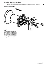
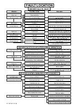
Mains connection and fuse in accordance with local regulations.

171 425 09  01-01

If S6 is missing connection between L1 and L2.
If S9 is missing connection between T6 and T8.

Damper position

3N ~50/60H

Z

 400 V

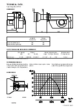
Содержание MOL 1650-3R B70 2-3

Страница 1: ...Installation Maintenance Manual MOL 1650 3R B70 2 3 Oil Burner 11 12 Tel 44 0 1905 794331 Fax 44 0 1905 794017 Email info nu way co uk Web www nu way co uk...

Страница 2: ...udeddisc 3 Nozzle 4 Nozzle assembly 5 Ignitionelectrodes 6 Ignitioncable 7 Ignitiontransformer 8 Photocell 9 Controlbox 10 Relay base 11 Dampermotor 12 Indicating lamp Stage 3 13 Cover inspectionglass...

Страница 3: ...dthespray patternchangewiththepumppressure state a definite spray angle or spray pattern Lengthof Flange burner tube Measure B BurnerheadStandard 364 324 BurnerheadLongdesign 664 624 OUTPUTRANGEANDNOZ...

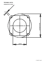
Страница 4: ...TECHNICAL DATA DIMENSIONS OF FLANGE 171 225 77 00 01 14 310 324 380 205 5...

Страница 5: ...Increase the nozzle assembly adjustment somewhat The CO2 con tent and consequently the air volume will then be reduced CONDENSATION IN CHIMNEY A modern burner works with less ex cess air and often al...

Страница 6: ...rds90 Adjust the operating switch back to stage 1 and check Stage 2 Adjust the operating switch to stage 1 I Reduce the air volume Turnorangecamtowards0 Increase the air volume Turnorangecamtowards90...

Страница 7: ...ower at the main switch and cut off the oil supply 171 305 93 01 01 NOTE For maintenance of the brake plate nozzles electrodes etc when using a long design of the burner tube you havetoremovethenozzle...

Страница 8: ...Operating switch Stage 3 S9 Control thermostat Stage 3 S20 Main switch T1 Ignitiontransformer X1 Connectionterminalboard X2 Earthterminal X3 Plug in contact Euro burner X4 Plug in contact Euro boiler...

Страница 9: ...r volume 22 s Safety time 5 s Post ignition time 15 s IntervalbetweenMv1andMv2 7 5 s Reset after lock out Immediately Time of re start 47 s Ambienttemperature 20 to 60 C Min required current at 220 V...

Страница 10: ...sumoftheseindividualresistances is so insignificant that they can be disregarded The tables do not include any lengths exceeding 100 m as experience shows that longer lengths are not needed Thetablesa...

Страница 11: ...so that there is a free passage back to the suction side through the return line with the return port closed EXCHANGE OF FILTER 171 505 39 94 02 One pipe system FUNCTION DANFOSS RSA 95 125 When the pu...

Страница 12: ...ge 1 2 Nozzle Stage 2 3 Nozzle Stage 3 4 Solenoid valve Stage 1 5 Solenoid valve Stage 2 6 Solenoid valve Stage 3 and adjustment device nozzle assembly 7 Oilpump 8 Adjustment device nozzle assembly 9...

Страница 13: ...255 219 22 43 266 229 23 34 277 238 24 23 287 247 25 07 297 256 25 91 307 264 26 70 317 272 6 00 22 34 265 228 23 42 278 239 24 47 290 250 25 46 302 260 26 43 313 270 27 49 326 280 28 27 335 288 29 1...

Страница 14: ......

Страница 15: ...not reset Appliance overheat device has operated Control relay or Photo cell defective Adjust thermostat Check by replacement Motor runs Burner runs to lockout No oil being delivered Excessive flue d...

Страница 16: ...NOTES...

Страница 17: ...NOTES...

Страница 18: ...Enertech Limited P O Box 1 Vines Lane Droitwich Worcestershire WR9 8NA Tel 44 0 1905 794331 Fax 44 0 1905 794017 Email info nu way co uk Web www nu way co uk...

Отзывы: