background image


2937 Alt Boulevard / PO Box 310 / Grand Island, NY 14072-0310 / 

PHONE

 716 773 7634 / 

FAX

 716 773 7744 / 

EMAIL

 [email protected] / 

WEB


www.nrdinc.com


Error! Unknown switch argument.


6211_6212_Manual_03/15 

6.


Input Power Connector - Plug for power adapter. 

7.


FMS (Facility Monitoring System) - FMS will allow you to monitor the status of ionizers and alarm connection. 

8.


DC Power Terminal - 24V DC power connects from process tool when possible. 

9.


Top LED - Green LED indicates when ionizer(s) is working properly or normal condition. 
High flashing LED will allow you to see indicator from a long distance. 

10.


Top LED - Red LED will indicate when ionizer(s) is in abnormal condition. 
High flashing LED will allow you to see indicator from a long distance. 

Note: Model 6212 has a single LED that activates in two colors, Green and Red. 

11.


Filter Cover - Easy filter cover release design. 

12.


Filter Cover Holding Clip (Model 6212) - Releases filter cover from enclosure. 

13.


Power Cable Clip (Model 6212) - Cable holding clip to avoid inadvertent unplugging. 

14.


Power Switch - Power ON/OFF and Air Flow Switch (Left: High, Middle: Off, Right: Low) 


2. Installation 

2-1. Locate the Staticmaster

®


300mm to 1200mm from the target to be neutralized for optimal performance, making sure that the airflow 
will not be restricted. 


A working electrical outlet within reach of the 1.8m (6’) long detachable cord that is supplied with the 
Staticmaster

®

2-2.


The Staticmaster

®

 can be installed in two different ways: 


Placed or secured on a flat surface such as a bench top. 


It can also be wall or shelf mounted to keep valuable bench space free for other purposes and equipment. 

2-3.


Power Connection 


Connect the barrel plug of the AC adapter to the receptacle in the back of the Staticmaster

®


Connect the AC adapter to a 120 VAC, 60 Hz electrical outlet. 

2-4.


Turn the Staticmaster

®

 “ON”. 

2-5.


Adjust the Staticmaster

®

 to direct the airflow into the work area. 


3. FMS Connection 

3-1 . Interface Terminal Connection 

Model 6211 

Pin No. 

Description 


Facility Monitoring System Output Signals 

FMS 1   Alarm relay output 

   Condition 

FMS 1~2 

FMS 2~3 

FMS 4~5 

FMS 2   Relay common 

   Normal state 

Open 

Closed 

4~5mA 

FMS 3   Normal relay output 

   Alarm State 

Closed 

Open 

17~20mA 

FMS 4   Current output for each operation     No Power 

Closed 

Open 

0mA 

FMS 5   Current output reference ground     


Содержание Staticmaster 6211

Страница 1: ...nd Descriptions 1 1 Features 1 2 Descriptions 2 Installation 2 1 Basic Installation 2 2 Inside or Outside of Process Tool 2 3 Recommended Installation Guideline 2 4 Power Connection 3 FMS Connection 3 1 Interface Terminal Connection 3 2 Interface Terminal Cabling 2 2 4 4 4 Maintenance 4 1 Filter Cover Attach and Release 4 2 Emitter Point Cleaning 4 3 Filter Cover Cleaning 4 4 Emitter Point Replace...

Страница 2: ...and generates high voltage Do not open and modify it or operate without being completely assembled High voltage internal parts can cause electrical shock WARNING Before performing maintenance turn the Staticmaster off and disconnect from the power source High voltage internal parts can cause electrical shock WARNING Do not use this product in a flammable atmosphere WARNING Do not submerge in water...

Страница 3: ...l_03 15 1 2 Descriptions Model 6211 Model 6212 1 Operation LED Green LED indicates that the ionizer is working properly or normal condition 2 Alarm LED Red LED indicates that ionizer is in abnormal condition 3 ON OFF Switch Power ON OFF Switch 4 Stand Refer to section 8 for dimensions of the mounting holes 5 Knob Direct ionizer at target and tighten knob to hold ionizer in place ...

Страница 4: ...N OFF and Air Flow Switch Left High Middle Off Right Low 2 Installation 2 1 Locate the Staticmaster 300mm to 1200mm from the target to be neutralized for optimal performance making sure that the airflow will not be restricted A working electrical outlet within reach of the 1 8m 6 long detachable cord that is supplied with the Staticmaster 2 2 The Staticmaster can be installed in two different ways...

Страница 5: ... Open FMS 3 Balance Alarm relay output Alarm Closed 17 20mA Closed FMS 4 Current output for each operation Power OFF Closed 0mA Closed FMS 5 Current output reference ground FMS 6 Balance Relay common 3 2 Interface Terminal Cabling 4 Maintenance Turn power off prior to regular maintenance or emitter point cleaning 4 1 Filter Cover Attach and Release Model 6211 Press filter cover slightly on the sid...

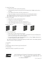
Страница 6: ...n enclosure Clean filter cover with water or compressed air After cleaning make sure ionizer is dry before turning power on If there is any damage on the filter cover it is recommended to replace it Model 6211 Filter Cover Model 6212 Filter Cover 4 4 Emitter Point Replacement Remove filter cover from rear panel of main enclosure Remove emitter points from sockets by gently pulling toward the middl...

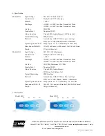
Страница 7: ...BS Black Bracket Aluminum Operating Environment Temperature 15 35 Humidity 35 85 RH Dimensions WxHxD 125x135x69 5mm with bracket 152x154 5x69 5mm Weight 571g with bracket Model 6212 Input Voltage 24V DC 13W Maximum Ion Emission Steady State DC Technology Balance 20V Discharge 1000V to 100V less than 2 seconds at 30cm 1000V to 100V less than 4 seconds at 60cm Air flow 140 CFM Maximum 151 CFM Emitte...

Страница 8: ...for a Return Authorization number and shipping instructions Include a copy of your original packing slip invoice or other proof of purchase date If the ionizer is out of warranty NRD LLC will quote repair charges necessary to bring your ionizer up to factory standards Warranty Exclusions The forgoing express warranty is made in lieu of all other product warranties expressed and implied including m...

Отзывы: