


Ethernet Configuration
Chapter 4
ProPak6 Installation and Operation User Manual 4
79
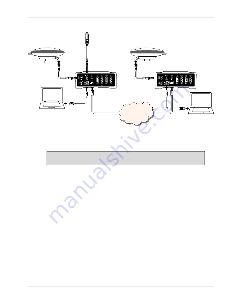
Figure 26: Base/Rover Ethernet Setup—ProPak6
1. Connect your computer to both ProPak6 receivers using null modem serial cables or USB cables.
2. Establish a connection to the receiver using either NovAtel Connect or another terminal program
such as Windows HyperTerminal. This connection is used to send the commands in this procedure to
the receivers.
3. Connect the power cables to both of the ProPak6 receivers and apply power to the receivers.
4. Connect the Ethernet cables to the Ethernet ports on both ProPak6 receivers.
5. Establish an Ethernet connection, either static or dynamic configurations. Refer to
IP Address Configuration on page 73
Section 4.3 Dynamic IP Address Configuration on page 77
for more information.
6. Send the following commands to each receiver either through serial or USB ports:
Base
:
fix position <lat> <long> <height>
interfacemode icom1 none rtca off
log icom1 rtcaobs2 ontime 1
log icom1 rtcaref ontime 10
log icom1 rtca1 ontime 5
saveconfig
Rover
:
icomconfig icom1 tcp <base ip address>:<base port #>
interfacemode icom1 rtca none off
log bestposa ontime 1 (optional)
saveconfig
Use the BESTPOS log to confirm that the ProPak6 rover is in RTK mode.
ProPak6
ProPak6
Computer
Computer
Antenna
Antenna
Antenna
Cable
Antenna
Cable
Ethernet
Cable
Ethernet
Cable
Network
Power Cable
USB Cable
USB Cable
For information about establishing a connection using NovAtel Connect, refer to the
Quick Start Guide for the product or NovAtel Connect Help.


