Introduction
Chapter 1
WAAS GUS Signal Generator User Guide Rev 1
13
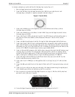
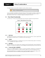
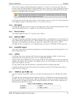
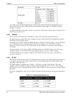
Figure 2: Signal Generator
1.1
Features
The Signal Generator has the following standard features:
• 19” rack-mountable 3U stainless steel enclosure
• NovAtel's advanced Signal Generator technology
1.2
Accessories and Options
The Signal Generator can be used with the following accessories:
• Power cable to connect the Signal Generator to a 100 to 240 V AC power source
• Optional Data Source Modules (used in a test environment and for firmware loading)
• Optional coaxial cables for the TNC and Type-N connectors on the Signal Generator
• Optional (WAAS G-III) Receiver
Should you need to order an accessory or a replacement part, contact NovAtel.
1.3
Functional Overview
The Signal Generator is comprised of two independent L1 and L5 generators which precisely control the frequency
and phase of L1/L5 code and carrier signals and generate two independent L1 and L5 70 MHz IF signals. The L1 IF
output has the L1 message structure with a factory configurable IF bandwidth of 2, 4 or 22 MHz for the Signal
Generator. The L5 IF output has the L5 signal structure with an IF bandwidth of 22 MHz.
The Signal Generator provides two loopback signals that are monitored by the WAAS G-III Receiver. These RF
signals are frequency upconverted replicas of the 70 MHz L1 and L5 outputs. By default, the 70 MHz L1 is
upconverted to 1227.6 MHz. Similarly, by default, the 70 MHz L5 is upconverted to 1176.45 MHz. The user can
select alternate RF frequencies of 1575.42 MHz for the L1 signal and 1227.6 MHz for the L5 signal.
The L1 and L5 Signal Generators share a common 10 MHz frequency source from the GUS frequency standard and
a 1PPS timing reference from the GUS receiver. The command and status interface between the Signal Generator
and the WAAS GUS Message Processor (WMP) is independent for L1 and L5. Similarly, the message interface
with the Comparator Message Processor (CMP) is independent for L1 and L5. This allows for independent L1 and
L5 control and message data streams.
The primary signals generated are output on 70 MHz IF carriers which, outside the unit, are subsequently frequency
upconverted to the necessary uplink frequencies. The Signal Generator contains facilities to precisely control the
frequency and phase of both the code modulation and carrier of the generated signals.


