62
IMS-MN-LMDE42C_A
Basics
Liberty MDrive Ethernet TCP/IP
Loss of Synchronization
Synchronous motion in a stepper motor requires that the lead/lag relationship between the
rotor and stator be /- 2 motor full steps. As this relationship drifts toward the 2 step
point the torque available to the load is reduced, with maximum constant torque available at
the <= 1 full step point.
Conditions that can cause the stepper motor to lose synchronization and stall are:
Rotor lags stator:
• Acceleration is too rapid to apply enough torque to overcome the inertia of the load.
• Transient load condition at velocity (i.e., load being increased on a conveyor).
Rotor leads stator:
• Deceleration is too rapid to hold the load within the +/- 2 full step range.
• Overhauling load condition where the momentum of the load is greater than the torque
supplied to maintain constant velocity.
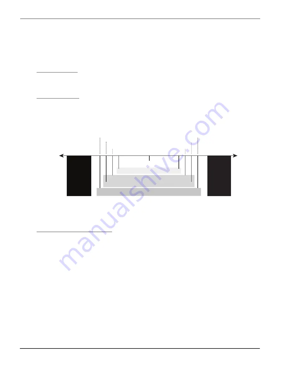
The following graphic shows control bounds for hMT.
Stall zone
> 2 full steps
Stall zone
> 2 full steps
1.1
1.3
1.5
1.7
1.7
1.5
1.3
1.1
0
Best speed performance
Best overall performance
Best torque performance
hMT maintains the rotor/stator relationship
within the set control bounds
LEAD
LAG
Hybrid Motion Technology uses a high speed feedback loop to tightly maintain the rotor -
stator relationship within a specified range, or control bounds.
Refer to the Ethernet Fieldbus Manual for additional information, available for download from:
https://novantaims.com/dloads/
Variable Current Control
Stepper motor drivers operate at two adjustable current levels:
1. Running current, the current level in use when the shaft is moving.
2. Holding or reduction current, the current level in use when the shaft is at rest.
Variable current control uses hMT to accurately measure and track the rotor/stator relationship
and apply current as needed. An example of this can be seen when current is applied during
acceleration or deceleration. The current is reduced to the level required to move the load when
the axis is at velocity. This can lead to greater power efficiency and reduced motor operating
temperatures.
Position Make-up
When active, the position make-up function stores the difference between commanded pulses
and actual motor steps in a register. At the completion of the move the lead or lag pulses will
be reinserted into the profile and moved to the commanded position at one of two velocity
presets.


