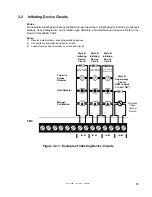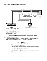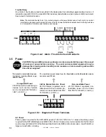
SFP-400B 15124:G1 06/24/97
17
3.4
Output Circuits
Notification Appliance Circuits
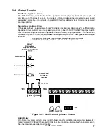
The SFP-400B can provide two Notification Appliance Circuits (Style Y). Each circuit is capable of
providing up to 1.5 amps of current. Total current for both circuits and the unregulated power cannot
exceed 2.25 amps. Refer to the Device Compatibility Chart for suitable devices. Circuits are supervised
and power-limited.
Supervisory Appliance Circuit
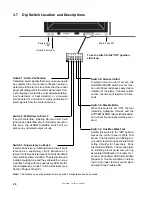
If Supervisory Input is selected (see Section
"Dip Switch Location and Descriptions" ), both Notification
Appliance Circuits will activate for supervisory conditions (either the SUPV1 or SUPV2 jumper must be
cut). To activate only one Notification Appliance Circuit (Circuit 2), cut jumper SUPV 1. To disable both
Notification Appliance Circuits, cut jumper SUPV 2 for supervisory conditions. (See figure below for jumper
location.)
If a 4XZM Relay Module is used, Relay 4 will activate for supervisories.
If an RZA-4X is used, the red LED 4 will annunciate supervisories.
Polarized Bell
Polarized Strobe
Polarized Horn
Style Y
Notification
Appliance Circuit
4.7K, 1/2-Watt (part # 71252 UL listed)
Dummy Load
all unused
Circuits
4.7K, 1/2-Watt
B+ B- B+ B-
TB4
TB3
Alarm Relay
One Form-C dry alarm contact is provided in the basic panel for controlling supplementary devices. It is
rated 2 amps at 30 VDC and 0.5 amps at 30 VAC (resistive) and is non-silenceable when an alarm occurs.
See the following page for terminal location.
JP1
SUPV1
OUT #1
OUT #2
SUPV2
Figure 3.4-1: Notification Appliance Circuits

