


11
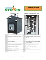
(A) MAIN POWER 15A FUSE
Main Power 15A, 250V, GDL, time delay fuse
(B) HIGH / LOW TEMP ALARM INDICATOR
This indicator will illuminate red when the furnace is
above or below the upper and lower limits preset in the
controller. The upper and lower limits act as an
additional failsafe and if the furnace reaches either one,
the furnace will shut down.
LOWER TEMP (Lower limit) = 120 ºF (48.9 ºC)
HIGH TEMP (Upper limit) = 200 ºF (93.3 ºC)
Note: Overheating the furnace above the upper limit of
200 ºF (93.3 ºC) can cause damage to the furnace and
components.
(C) START PUSH BUTTON
Once fuel is lit, turn the selector switch “
SYSTEM
OFF – ON ILLUMINATED SWITCH (D)
” to
ON
and press the “
START
” button. This tells the
controller (H) to take over and maintain the operation of
the system.
(D) SYSTEM OFF – ON ILLUMINATED SWITCH
This switch must be turned
ON
for the controller
system to function correctly. The switch will illuminate
red if left in the
OFF
position. This is a reminder to the
operator to turn the switch
ON
for normal operation.
Note: The auxiliary receptacles on the bottom of the
Electronic Control System are NOT affected by turning
the switch
ON
or
OFF
. The auxiliary receptacles are
intended for the circulating pumps and accessories.
(E) BLOWER / SOLENOID 10A FUSE
Blower / Solenoid 10A, 250V, GDL, time delay fuse
(F) LOW WATER ALARM INDICATOR
This indicator will illuminate red in the event that the water
jacket is getting low on water. If this is lit red, then the furnace
will shut down until the water jacket is topped up with water.
Do not ignore or bypass this indicator! Damage to the furnace
and components can occur if water is not added to the system.
(G) INTERIOR LIGHT OFF – ON SWITCH
This switch will turn
ON
and
OFF
the interior light within
the Control House allowing for inspection and maintenance
during dim or dark ambient lighting conditions.
Electronic Control
System
Содержание 30-30
Страница 23: ...21 Notes...