North Star NSRO42C4 Скачать руководство пользователя страница 4

4

Supply water pressure limits  . . . . . . . . . . . . . . . . . . . . . . . . . . . . . . . . . . . . . . . . . . . . . . 40-100 psi (280-689 kPa)

Supply water temperature limits  . . . . . . . . . . . . . . . . . . . . . . . . . . . . . . . . . . . . . . . . . . . . . 40-100 °F (4.5-37.7°C)

Maximum total dissolved solids (TDS)   . . . . . . . . . . . . . . . . . . . . . . . . . . . . . . . . . . . . . . . . . . . . . . . . . . 2000 ppm

Maximum water hardness @ 6.9 pH . . . . . . . . . . . . . . . . . . . . . . . . . . . . . . . . . . . . . . . . . . . . . . . . . . . . . . . 10 gpg

Maximum iron, manganese, hydrogen sulfide  . . . . . . . . . . . . . . . . . . . . . . . . . . . . . . . . . . . . . . . . . . . . . . . . . . . . 0

Chlorine in water supply (max. ppm)   . . . . . . . . . . . . . . . . . . . . . . . . . . . . . . . . . . . . . . . . . . . . . . . . . . . . . . . . . 2.0

Supply water pH limits (pH) . . . . . . . . . . . . . . . . . . . . . . . . . . . . . . . . . . . . . . . . . . . . . . . . . . . . . . . . . . . . . . . . 4-10

Product (quality) water, 24 hours

1

 . . . . . . . . . . . . . . . . . . . . . . . . . . . . . . . . . . . . . . . . . . . . . . 18.4 gal. (69.6 liters)

Percent rejection of TDS, minimum (new membrane)

1

 . . . . . . . . . . . . . . . . . . . . . . . . . . . . . . . . . . . . . . . . . . . 86.5

Automatic shutoff control  . . . . . . . . . . . . . . . . . . . . . . . . . . . . . . . . . . . . . . . . . . . . . . . . . . . . . . . . . . . . . . . . . . yes

Efficiency

2

 . . . . . . . . . . . . . . . . . . . . . . . . . . . . . . . . . . . . . . . . . . . . . . . . . . . . . . . . . . . . . . . . . . . . . . . . . . 12.2 %

Recovery

3

 . . . . . . . . . . . . . . . . . . . . . . . . . . . . . . . . . . . . . . . . . . . . . . . . . . . . . . . . . . . . . . . . . . . . . . . . . . . 22.9 %

This system conforms to NSF/ANSI 58 for the specific performance claims as verified and substantiated by test data.

1

@ Feed water supply at 50 psi, 77°F, and 750 TDS --- Quality water production, amount of waste water and percent rejection

all vary with changes in pressure, temperature and total dissolved solids.

2

Efficiency rating means the percentage of the influent water to the system that is available to the user as reverse osmosis treat-

ed water under operating conditions that approximate typical daily usage.

3

Recovery rating means the percentage of the influent water to the membrane portion of the system that is available to the user

as reverse osmosis treated water when the system is operated without a storage tank or when the storage tank is bypassed.

Non-potable Water Sources: 

Do not attempt to use this product to make safe drinking water from non-potable water sources.

Do not use the system on microbiologically unsafe water, or water of unknown quality without an adequate disinfection before or

after the system. This system is certified for cyst reduction and may be used on disinfected water that may contain filterable

cysts.

Arsenic Reduction: 

This system shall only be used for arsenic reduction on chlorinated water supplies containing detectable

residual free chlorine at the system inlet. Water systems using an inline chlorinator should provide a one minute chlorine contact

time before the reverse osmosis system. 

Nitrate/Nitrite Test Kit: 

This system is acceptable for treatment of influent concentrations of no more than 27mg/L nitrate and

3mg/L nitrite in combination measured as N. It is certified for nitrate/nitrite reduction only for water supplies with a pressure of 280

kPa (40 psig) or greater. This system is supplied with a nitrate/nitrite test kit. Product water should be monitored periodically

according to the instructions provided with the test kit.

TDS Test Kits:

TDS test kits are available by calling 1-800-949-8220, or check the water testing section of your local phone

directory.

Installations In The Commonwealth Of Massachusetts: 

The Commonwealth of Massachusetts requires installation be per-

formed by a licensed plumber and do not permit the use of saddle valves. Plumbing code 248--CMR of the Commonwealth of

Massachusetts must be followed in these cases.

Product Water Testing:

The Reverse Osmosis System contains a replaceable treatment component critical for the effective

reduction of total dissolved solids. Product water should be tested periodically to verify that the system is performing properly. 

Replacement of the reverse osmosis component:

This reverse osmosis system contains a replaceable component critical to

the efficiency of the system. Replacement of the reverse osmosis component should be with one of identical specifications, as

defined by the manufacturer, to assure the same efficiency and contaminant performance.

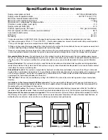
Specifications & Dimensions

12-1/4"

4-3/4"

13"

11" dia.

16"

4-3/4”

13”

16”

12-1/4”

11” dia.

FIG. 1

Содержание NSRO42C4

Страница 1: ...ons or concerns when installing operating or maintaining your reverse osmosis system call our toll free number 1 800 972 0135 Monday Friday 7 AM 6 PM CST in Canada please call 1 800 796 6784 or visit...

Страница 2: ...ns 4 Unpack and Check Shipment 5 Plan Your Installation 6 7 Overview Site Preparation 8 Installation Instructions 9 19 Step A Install Supply Water Fitting 9 Step B Install Reverse Osmosis Drain 10 11...

Страница 3: ...e alteration neglect freezing accident or negli gence and provided further that the Reverse Osmosis Drinking Water System is not damaged as the result of any unusual force of nature such as but not li...

Страница 4: ...rsenic Reduction This system shall only be used for arsenic reduction on chlorinated water supplies containing detectable residual free chlorine at the system inlet Water systems using an inline chlor...

Страница 5: ...ged in shipment Note any damage to the shipping carton Refer to the exploded view and parts list in the back of the manual for the part names and numbers of missing or damaged items If problems exist...

Страница 6: ...tank may be installed in a kitchen or bathroom sink cabinet See Fig 4 A suitable drain point is needed for drain water from the Reverse Osmosis system REMOTE INTERIOR LOCATION The Reverse Osmosis Filt...

Страница 7: ...Cold Water Supply Storage Tank Sink Drain P Trap Shutoff Valve Reverse Osmosis Assembly HOT COLD Tee Feed Adaptor Outside Faucet Hard Water Soft Cold Water Soft Hot Water Outside Faucet Hard Water Wat...

Страница 8: ...efore starting close the hot and cold water shutoff valves See Figure 7 2 Temporarily place tank and filter assembly into planned location Check position of items and space required for proper install...

Страница 9: ...alves If you live in the state of Massachusetts review plumb ing code 248 CMR of the Commonwealth of Massachusetts before proceeding with the installation INSTALL COLD WATER SUPPLY FITTING Included wi...

Страница 10: ...r 1 Slowly disassemble the sink drain pipe between the sink P trap and the sink tailpiece See Fig 8 10 2 Clean the sink tailpiece to assure a leak tight fit 3 Install drain adapter directly onto the s...

Страница 11: ...back of manual may be needed 3 If longer tubing is required disconnect the 1 4 red tubing and replace with an adequate length of tubing to reach the drain point Refer to Step F later in the manual on...

Страница 12: ...g steps to install your Reverse Osmosis Filter Assembly 1 Remove the cover 2 Locate mounting slots on back inside of the assem bly See Fig 13 3 Hold the assembly up to the wall surface and mark locati...

Страница 13: ...nipple at the top of the tank See Fig 14 2 Locate the tubing connector See Fig 14 Tighten the tubing connector onto the tank nipple 7 8 full turns being careful not to cross thread or overtighten 3 D...

Страница 14: ...e the existing sink top hole for the spray hose or soap dispenser Must be 1 1 4 in diameter Drill a new hole in the sink Drill a new hole in the countertop next to the sink 1 Determine where you are g...

Страница 15: ...regard step 5 and move on to step 6 5 Route the 1 4 red tubing from the bottom up through the faucet mounting hole Push the end of the tubing onto the 1 4 barb fitting See Fig 17 NOTE Tubing lengths s...

Страница 16: ...collet until it engages the o ring See Fig 20 Continue pushing until the tube bottoms out against the back of the fitting See Fig 21 Do not stop pushing when the tube engages the o ring Failure to fol...

Страница 17: ...4 Insert all the way into the fitting See Figs 20 21 5 Pull on the tube to be sure it s held firmly in the fitting CONNECT BLACK TUBE FROM REVERSE OSMOSIS FAUCET TO DRAIN ADAPTER 1 Locate the 3 8 bla...

Страница 18: ...the Reverse Osmosis system is off 2 Open the Reverse Osmosis faucet If the tank is not already empty allow the water to empty 3 Locate the eyedropper included in parts bag and common household bleach...

Страница 19: ...system is producing water even if you are not drawing water from the Reverse Osmosis faucet You may hear a small quantity of water going to the drain at times when water is not being used This is norm...

Страница 20: ...has a hand operated knob to dispense drinking water See Fig 28 An air gap is built into the faucet drain water connection to comply with plumbing codes See Fig 28 FAUCET ELECTRONICS The RO system wil...

Страница 21: ...to the storage tank 5 Drain water with dissolved solids leaves the Reverse Osmosis membrane and flows to the drain 6 Faucet is activated 7 Processed water leaves the storage tank and flows to the post...

Страница 22: ...he following steps to replace the cartridges NOTE Do not remove manifold from mounts Flexing or twisting may damage the manifold 1 Remove turn to the left the prefilter cartridge from the manifold to...

Страница 23: ...in the manifold when the push in elbow fitting is removed you will need to remove the drain port s collet and o ring as shown in the next sec tion to retrieve it CHANGE COLLET AND O RING 1 Remove the...

Страница 24: ...lter cartridge and Reverse Osmosis membrane cartridge See Page 22 Problem System makes lower amount of product water than usual Cause Storage tank air charge less than 5 7 psi Correction Open Reverse...

Страница 25: ...bing square See pages 16 17 Cause Tubing not pushed in all the way Correction Push tubing in all the way See pages 16 17 Cause Tubing nicked Correction Remove tube from connection Remove nicked portio...

Страница 26: ...26 Exploded View 28 27 26 24 23 22 21 20 1 4 red tubing 18 13 10 9 7 6 4 5 3 1 2 25 11 16 17 15 19 8 14 12 6...

Страница 27: ...11 Screw 2 req d 12 Cover Paddlewheel 13 Paddlewheel 14 O Ring Paddlewheel Key No Part No Description 15 7296521 Rep l Manifold Assembly includes Key Nos 1 8 11 14 7333129 Mounting Hardware Kit inclu...

Страница 28: ...DBURY MN 55125 PARTS RETURN TAG CUSTOMER S NAME STREET ADDRESS STATE DATE PURCHASED DATE PART FAILED R O MODEL NUMBER SERIAL NUMBER CITY ZIP CODE NORTH STAR WATER CONDITIONING 1890 WOODLANE DRIVE WOOD...

Отзывы: