North Star NSRO42C4 Скачать руководство пользователя страница 22

22

Maintenance

PREFILTER/POSTFILTER MAINTENANCE

NOTE: It is recommended to replace the battery,

prefilter and postfilter cartridges at least every 6

months of product water use. Replace more often if

they begin to plug with sediment. 

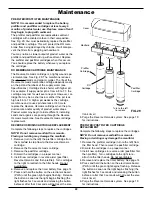
The prefilter and postfilter are replaceable sediment

cartridges with activated carbon in their composition.

See Fig. 29. You must periodically replace the prefilter

and postfilter cartridge. This will  protect the RO mem-

brane from being destroyed by chlorine. It will also pre-

vent the filters from plugging with sediment.
You may notice a slower output of product water as the

prefilter and postfilter build up with sediment. Replace

the prefilter and postfilter cartridges when this occurs.

You should replace the battery whenever you replace

the cartridges.

RO MEMBRANE CARTRIDGE MAINTENANCE

The Reverse Osmosis cartridge is a tightly wound spe-

cial membrane. See Fig. 29. The membrane reduces

the 

dissolved

solids and organic matter. The life of the

Reverse Osmosis membrane cartridge depends mostly

on the pH and hardness of the supply water (see

Specifications). Cartridge life is shorter with higher pH.

For example, if supply water pH is from 6.8 to 7.7, the

cartridge may last for well over one year. However, car-

tridge life may be as short as 6 months if the pH is as

high as 8.5 to 10. Higher pH weakens the cartridge

membrane and causes pin-hole leaks. It's time to

replace the Reverse Osmosis cartridge when the pro-

duction rate and/or quality of product water drops.

Product water may begin to taste different, indicating

solids and organics are passing through the Reverse

Osmosis membrane. See Reverse Osmosis cartridge

replacement.

REVERSE OSMOSIS CARTRIDGE REPLACEMENT

Complete the following steps to replace the cartridges.

NOTE: Do not remove manifold from mounts.

Flexing or twisting may damage the manifold.

1. Remove (turn to the left) the prefilter cartridge from

the manifold to stop flow to the Reverse Osmosis

cartridge.

2. Remove the Reverse Osmosis cartridge.

3. Remove the postfilter cartridge.

4. Discard the cartridges in a proper manner. 

5. Install new cartridges in reverse order (post filter,

Reverse Osmosis and then prefilter). Turn cartridges

to the right to reattach to the filter heads. Do not

overtighten.

6. Remove and replace the timer battery. See page 14.

7. Press and hold the button on the electronics board

(PWA) until the green light begins flashing.  Release

the button as soon as the light begins flashing (the

light flashes for 3 seconds and releasing the button

before or after that 3 seconds will not reset the elec-

tronic timer).

8. Purge the Reverse Osmosis system. See page 19

for instructions.

PREFILTER/POSTFILTER CARTRIDGE

REPLACEMENT

Complete the following steps to replace the cartridges.

NOTE: Do not remove manifold from mounts.

Flexing or twisting may damage the manifold.

1. Remove the prefilter cartridge (turn to the left) from

the filter head. Then remove the postfilter cartridge.

2. Discard the cartridges in a proper manner. 

3. Install new cartridges in reverse order (postfilter first,

then prefilter). Turn cartridges to the right to re-

attach to the filter heads. Do not overtighten.

4. Remove and replace the timer battery. See page 14.

5. Press and hold the button on the electronics board

(PWA) until the green light begins flashing.  Release

the button as soon as the light begins flashing (the

light flashes for 3 seconds and releasing the button

before or after that 3 seconds will not reset the elec-

tronic timer).

6. Purge the Reverse Osmosis system. See page 19

for instructions.

FIG. 29

Cover

Prefilter

Cartridge

Manifold

Postfilter

Cartridge

RO

Cartridge

Turn to the left

to remove

Содержание NSRO42C4

Страница 1: ...ons or concerns when installing operating or maintaining your reverse osmosis system call our toll free number 1 800 972 0135 Monday Friday 7 AM 6 PM CST in Canada please call 1 800 796 6784 or visit...

Страница 2: ...ns 4 Unpack and Check Shipment 5 Plan Your Installation 6 7 Overview Site Preparation 8 Installation Instructions 9 19 Step A Install Supply Water Fitting 9 Step B Install Reverse Osmosis Drain 10 11...

Страница 3: ...e alteration neglect freezing accident or negli gence and provided further that the Reverse Osmosis Drinking Water System is not damaged as the result of any unusual force of nature such as but not li...

Страница 4: ...rsenic Reduction This system shall only be used for arsenic reduction on chlorinated water supplies containing detectable residual free chlorine at the system inlet Water systems using an inline chlor...

Страница 5: ...ged in shipment Note any damage to the shipping carton Refer to the exploded view and parts list in the back of the manual for the part names and numbers of missing or damaged items If problems exist...

Страница 6: ...tank may be installed in a kitchen or bathroom sink cabinet See Fig 4 A suitable drain point is needed for drain water from the Reverse Osmosis system REMOTE INTERIOR LOCATION The Reverse Osmosis Filt...

Страница 7: ...Cold Water Supply Storage Tank Sink Drain P Trap Shutoff Valve Reverse Osmosis Assembly HOT COLD Tee Feed Adaptor Outside Faucet Hard Water Soft Cold Water Soft Hot Water Outside Faucet Hard Water Wat...

Страница 8: ...efore starting close the hot and cold water shutoff valves See Figure 7 2 Temporarily place tank and filter assembly into planned location Check position of items and space required for proper install...

Страница 9: ...alves If you live in the state of Massachusetts review plumb ing code 248 CMR of the Commonwealth of Massachusetts before proceeding with the installation INSTALL COLD WATER SUPPLY FITTING Included wi...

Страница 10: ...r 1 Slowly disassemble the sink drain pipe between the sink P trap and the sink tailpiece See Fig 8 10 2 Clean the sink tailpiece to assure a leak tight fit 3 Install drain adapter directly onto the s...

Страница 11: ...back of manual may be needed 3 If longer tubing is required disconnect the 1 4 red tubing and replace with an adequate length of tubing to reach the drain point Refer to Step F later in the manual on...

Страница 12: ...g steps to install your Reverse Osmosis Filter Assembly 1 Remove the cover 2 Locate mounting slots on back inside of the assem bly See Fig 13 3 Hold the assembly up to the wall surface and mark locati...

Страница 13: ...nipple at the top of the tank See Fig 14 2 Locate the tubing connector See Fig 14 Tighten the tubing connector onto the tank nipple 7 8 full turns being careful not to cross thread or overtighten 3 D...

Страница 14: ...e the existing sink top hole for the spray hose or soap dispenser Must be 1 1 4 in diameter Drill a new hole in the sink Drill a new hole in the countertop next to the sink 1 Determine where you are g...

Страница 15: ...regard step 5 and move on to step 6 5 Route the 1 4 red tubing from the bottom up through the faucet mounting hole Push the end of the tubing onto the 1 4 barb fitting See Fig 17 NOTE Tubing lengths s...

Страница 16: ...collet until it engages the o ring See Fig 20 Continue pushing until the tube bottoms out against the back of the fitting See Fig 21 Do not stop pushing when the tube engages the o ring Failure to fol...

Страница 17: ...4 Insert all the way into the fitting See Figs 20 21 5 Pull on the tube to be sure it s held firmly in the fitting CONNECT BLACK TUBE FROM REVERSE OSMOSIS FAUCET TO DRAIN ADAPTER 1 Locate the 3 8 bla...

Страница 18: ...the Reverse Osmosis system is off 2 Open the Reverse Osmosis faucet If the tank is not already empty allow the water to empty 3 Locate the eyedropper included in parts bag and common household bleach...

Страница 19: ...system is producing water even if you are not drawing water from the Reverse Osmosis faucet You may hear a small quantity of water going to the drain at times when water is not being used This is norm...

Страница 20: ...has a hand operated knob to dispense drinking water See Fig 28 An air gap is built into the faucet drain water connection to comply with plumbing codes See Fig 28 FAUCET ELECTRONICS The RO system wil...

Страница 21: ...to the storage tank 5 Drain water with dissolved solids leaves the Reverse Osmosis membrane and flows to the drain 6 Faucet is activated 7 Processed water leaves the storage tank and flows to the post...

Страница 22: ...he following steps to replace the cartridges NOTE Do not remove manifold from mounts Flexing or twisting may damage the manifold 1 Remove turn to the left the prefilter cartridge from the manifold to...

Страница 23: ...in the manifold when the push in elbow fitting is removed you will need to remove the drain port s collet and o ring as shown in the next sec tion to retrieve it CHANGE COLLET AND O RING 1 Remove the...

Страница 24: ...lter cartridge and Reverse Osmosis membrane cartridge See Page 22 Problem System makes lower amount of product water than usual Cause Storage tank air charge less than 5 7 psi Correction Open Reverse...

Страница 25: ...bing square See pages 16 17 Cause Tubing not pushed in all the way Correction Push tubing in all the way See pages 16 17 Cause Tubing nicked Correction Remove tube from connection Remove nicked portio...

Страница 26: ...26 Exploded View 28 27 26 24 23 22 21 20 1 4 red tubing 18 13 10 9 7 6 4 5 3 1 2 25 11 16 17 15 19 8 14 12 6...

Страница 27: ...11 Screw 2 req d 12 Cover Paddlewheel 13 Paddlewheel 14 O Ring Paddlewheel Key No Part No Description 15 7296521 Rep l Manifold Assembly includes Key Nos 1 8 11 14 7333129 Mounting Hardware Kit inclu...

Страница 28: ...DBURY MN 55125 PARTS RETURN TAG CUSTOMER S NAME STREET ADDRESS STATE DATE PURCHASED DATE PART FAILED R O MODEL NUMBER SERIAL NUMBER CITY ZIP CODE NORTH STAR WATER CONDITIONING 1890 WOODLANE DRIVE WOOD...

Отзывы: