


19
Step G - Sanitize, Test and Purge System (cont.)
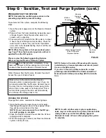
PRESSURE TEST THE SYSTEM
NOTE: Complete the sanitizing procedures on the
preceding page before pressure testing.
To pressure test the system, complete the following
steps.
1. Open the water supply valve to the Reverse Osmosis
system.
2. Purge air from the house plumbing by opening sever-
al house faucets. Close faucets when water runs
smooth, with no spurting.
3. Pressure will start to build in the RO system. In about
2 hours check all fittings and connections. Check for
water leaks. Fix leaks if any are found. If problems
exist, refer to the troubleshooting chart or call the toll
free number below).
NOTE: When the system is first pressurized, water
may ''spurt'' from the faucet air gap hole until air is
expelled from the RO system.
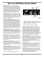
Please review the following operating features
before using your Reverse Osmosis system:
You will
not
have filtered water immediately. It may
take several hours to fill the storage tank and create
maximum flow from the Reverse Osmosis faucet.
Water Pressure from the Reverse Osmosis faucet will
be less than your standard faucet.
Water will run to the drain while the Reverse
Osmosis system is producing water, even if you are
not drawing water from the Reverse Osmosis faucet.
You may hear a small quantity of water going to the
drain at times when water is not being used. This is
normal. Water going to the drain will automatically
shut off when the storage tank is full.
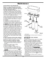
PURGING THE SYSTEM
To purge the system, complete the following steps.
1. Open the Reverse Osmosis Faucet and let water
flow through the system for a 24 hour period. Water
flow will be a slow trickle at this time.
NOTE: Do not consume water from the RO sys-
tem until purging is complete.
2. Close the Reverse Osmosis faucet after the 24 hour
purging period is complete.
3. When the purging is finished, your Reverse Osmosis
system is ready for use.
NOTE: As with all other water system applications,
leaks may occur. Because the system pressure builds
slowly, leaks may not be immediately apparent.
Recheck for leaks 24 hours after purging the system
is complete.
NOTE: Codes in the state of Massachusetts require
installation by a licensed plumber and do not permit
the use of saddle valves.
If you live in the state of Massachusetts, review
plumbing code 248-CMR of the Commonwealth of
Massachusetts before proceeding with the installa-
tion.
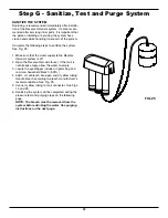
FIG. 26
Storage
Tank
Tee Feed
Adaptor
Water Supply Shutoff
Valve to Reverse
Osmosis System
HOT COLD
Reverse
Osmosis
Faucet
Kitchen
Faucet


