background image

Chapter 2 Contivity 100 unit hardware installation

29

Setting Up the Contivity 100 Unit


Figure 2

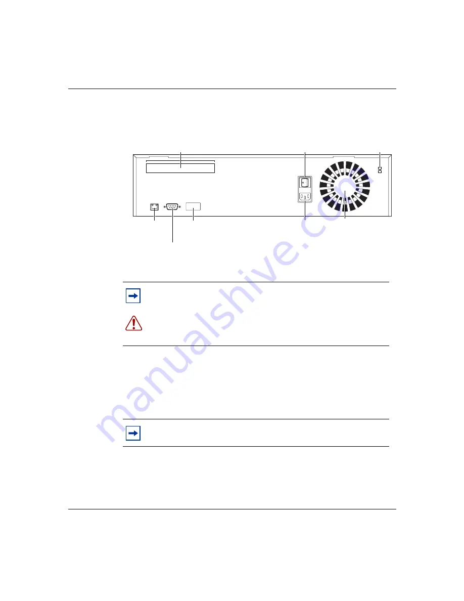
 illustrates the rear panel of the unit.

Figure 2   Rear panel of the Contivity 100 unit

Interfaces

Each unit has an autosensing, autonegotiating seven-port 10/100 Ethernet switch, 
a full-duplex/half-duplex autonegotiating Ethernet LAN interface, and one of 
several communications interface cards.

Note: 

If you have a triple-Ethernet unit, the third Ethernet connection 

(Eth3) replaces the phone jack or ISDN jack at the top of the unit.

Warning: 

Your Contivity 100 unit contains a lithium battery. There is a 

danger of explosion if the battery is replaced incorrectly. The battery 
should be replaced only by factory authorized personnel.

Note: 

The interface card(s) in your unit may not look exactly like those 

depicted in the illustrations.

Option card

(to telco or 

Ethernet device)

Eth2 connection

(to router

or bridge)

Power
switch

Fan

Configuration

switches

Power supply

connector

Power voltage

selector switch

9859EC

Aux

Configure

Ethernet

10/100

115 / 230 V ~

50 / 60 Hz , 4A / 2A

230VAC

115VAC

Link

Act

AUX port

(to PC

or modem)

Содержание Contivity 100

Страница 1: ...Part No 313369 A July 2001 4401 Great America Parkway Santa Clara CA 95054 Setting Up the Contivity 100 Unit ...

Страница 2: ...rporation UNIX is a trademark of X Open Company Limited The asterisk after a name denotes a trademarked item Statement of conditions In the interest of improving internal design operational function and or reliability Nortel Networks Inc reserves the right to make changes to the products described in this document without notice Nortel Networks Inc does not assume any liability that may occur due ...

Страница 3: ...elchen Fällen der Benutzer für entsprechende Gegenmaßnahmen verantwortlich ist Attention Ceci est un produit de Classe A Dans un environnement domestique ce produit risque de créer des interférences radioélectriques il appartiendra alors à l utilisateur de prendre les mesures spécifiques appropriées EC Declaration of conformity This product conforms to the provisions of the R TTE Directive 1999 5 ...

Страница 4: ...EN assigned to each terminal device provides an indication of the maximum number of terminals allowed to be connected to a telephone interface The termination on an interface may consist of any combination of devices subject only to the requirement that the sum of the Ringer Equivalence Numbers of all the devices does not exceed 5 The REN is located on the FCC Rules Part 68 label located on the br...

Страница 5: ...he Facility Interface Code 02IS5 The Service Order Code s SOC 6 0F The required Universal Service Order Code USOC jack RJ49C When you request ISDN S T Interface Service you must provide the telephone company with The Service Order Code s SOC 6 0N The make model number and FCC Registration number of the NT1 Note ISDN S T cannot be directly connected to the network When you request Primary Rate ISDN...

Страница 6: ...orbell wires wires from transformers to neon signs steam or hot water pipes and heating ducts Before working with existing inside wiring check all electrical outlets for a square telephone dial light transformer and unplug it from the electrical outlet Failure to unplug all telephone transformers can cause electrical shock Do not place a jack where it would allow a person to use the telephone whil...

Страница 7: ...iring and Powering Guidelines Residence and Small Business Avis L étiquette d Industrí Canada identifie le matériel homologué Cette étiquette certifie que le matériel est conforme à certaines normes de protection d exploitation et de sécurité des réseaux de télécommunications Toutefois le Ministére n assure pas que le matériel fonctionnera a la satisfaction de l utilisateur Avant d installer ce ma...

Страница 8: ...ee may not modify translate decompile disassemble use for any competitive analysis reverse engineer distribute or create derivative works from the Software or user manuals or any copy in whole or in part Except as expressly provided in this Agreement Licensee may not copy or transfer the Software or user manuals in whole or in part The Software and user manuals embody Nortel Networks and its licen...

Страница 9: ...ftware Directive enacted by the Council of European Communities Directive dated 14 May 1991 will apply to the examination of the Software to facilitate interoperability Licensee agrees to notify Nortel Networks of any such intended examination of the Software and may procure support and assistance from Nortel Networks 7 Term and termination This license is effective until terminated however all of...

Страница 10: ...L PRIOR ORAL AND WRITTEN AGREEMENTS AND COMMUNICATIONS BETWEEN THE PARTIES PERTAINING TO THE SUBJECT MATTER OF THIS AGREEMENT NO DIFFERENT OR ADDITIONAL TERMS WILL BE ENFORCEABLE AGAINST NORTEL NETWORKS UNLESS NORTEL NETWORKS GIVES ITS EXPRESS WRITTEN CONSENT INCLUDING AN EXPRESS WAIVER OF THE TERMS OF THIS AGREEMENT ...

Страница 11: ...7 Interfaces 29 Power cords 32 Setting the power voltage selector switch 34 Contivity 100 unit hardware installation 35 Mounting your Contivity 100 unit on a wall 38 Attaching the brackets to the Contivity 100 unit 39 Mounting the Contivity 100 unit on a wood wall 42 Preparing a wood wall for mounting 42 Mounting the Contivity 100 unit on a wood wall 42 Mounting the Contivity 100 unit on a drywall...

Страница 12: ...nd diagnostic functions 57 Interpreting Contivity 100 unit LEDs 57 LEDs 1 through 8 and Power LED at power up sequence 58 LEDs 1 through 8 and the Power LED during operation 59 Using the seven port autosensing Ethernet switch LEDs for troubleshooting 60 Chapter 6 Out of band management support 61 Configuring the Contivity 100 unit through a direct connection 62 Connecting the Contivity 100 unit di...

Страница 13: ...echnical specifications 71 Physical specifications 71 Electrical specifications 71 Environmental specifications 72 Appendix B Adapter cable pinout diagrams 73 Remote access adapter cables 73 Null modem adapter PC to PC cable 73 Modem adapter cable 74 Index 75 ...

Страница 14: ...14 Contents 313369 A ...

Страница 15: ...y 100 unit on the wall 43 Figure 7 Configuration switches on the rear panel of the unit 51 Figure 8 Contivity 100 unit LEDs 58 Figure 9 HyperTerminal Connection Description dialog box 64 Figure 10 HyperTerminal Connect To dialog box 64 Figure 11 HyperTerminal COM1 Properties dialog box 65 Figure 12 Command prompt 66 Figure 13 HyperTerminal Connection Description dialog box 67 Figure 14 HyperTermin...

Страница 16: ...16 Figures 313369 A ...

Страница 17: ...ttings for setting the AUX port speed to 9600 baud 52 Table 7 Switch settings for resetting the passwords 53 Table 8 Switch settings for resetting the passwords and user defined configurations 53 Table 9 Switch settings to disable switch settings for resetting the passwords and user defined configurations 54 Table 10 Switch settings for resetting factory default conditions 54 Table 11 LED status a...

Страница 18: ...18 Figures 313369 A ...

Страница 19: ...your unit Model ____________________________________________________ Example DM1401E67 Serial ____________________________________________________ Example I500E07BF224BB Second you must obtain Internet access from an Internet service provider ISP For details refer to Installing the Contivity Branch Access Management Software Version 7 20 Warning To avoid bodily injury from hazardous electrical sho...

Страница 20: ...P Dual Inline Pins DMZ Demilitarized Zone DSU Data Service Unit FDX Full Duplex HAR Harmonized HD Harmonized Document HDX Half Duplex IEC International Electrotechnical Commission ISDN Integrated Services Digital Network ISP Internet Service Provider Kb s Kilobits Per Second LAN Local Area Network LED Light Emitting Diode LIU Line Isolation Unit MB Megabyte Mb s Megabits Per Second MDI Medium Depe...

Страница 21: ...erminal Emulator Installing the Contivity Branch Access Management Software Version 7 20 part number 313367 A Provides instructions for installing the Contivity Branch Access management software NIC Network Interface Card NIUF National ISDN Users Forum NOM Norma Oficial Mexicana NT1 Network Termination Type 1 PC Personal Computer POTS Plain Old Telephone Service PPP Point to Point Protocol PPPoE P...

Страница 22: ...ng the Contivity Branch Access Management Software Version 7 20 Setting Up the Contivity 100 Unit Setting Up the Contivity 400 Unit Using the Contivity Branch Access Management Software Version 7 20 Reference for the Contivity Branch Access Command Line Interface Version 7 20 You can print selected technical manuals and release notes free directly from the Internet Go to the www nortelnetworks com...

Страница 23: ...ns Centers An Express Routing Code ERC is available for many Nortel Networks products and services When you use an ERC your call is routed to a technical support person who specializes in supporting that product or service To locate an ERC for your product or service go to the www nortelnetworks com servsup URL Click the Tools menu item and then click Express Routing Codes under the Other heading ...

Страница 24: ...24 Preface 313369 A ...

Страница 25: ...ftware and Documentation Version 7 20 CD part number 313374 A For contents see Related publications on page 21 Depending on the type of connection you ordered your Contivity 100 package contains one or more of the following connector cables RJ 11 cable phone cord for a dial up connection ISDN cable for an Integrated Service Digital Network ISDN connection Caution Before you install your unit make ...

Страница 26: ...nnection Internal single or dual analog modem Internal ISDN 128K card with or without NT1 with a Plain Old Telephone Service POTS connection Requirements and compatibility Your Contivity 100 unit supports the following Internet connection types Dial up Point to Point Protocol PPP connection with optional Multilink Protocol MP at up to two times V 90 ISDN connection using synchronous PPP and option...

Страница 27: ...pendix A Technical specifications on page 71 Getting to know your Contivity 100 unit The front panel of your Contivity 100 unit has the following indicators and connections Nine LEDs labeled 1 8 and Power indicate various active or error conditions for your unit For details refer to Chapter 5 LEDs support and diagnostic functions on page 57 Caution Before you install your unit make sure that the p...

Страница 28: ...port and diagnostic functions on page 57 Figure 1 illustrates the front panel of the unit Figure 1 Front panel of the Contivity 100 unit The rear panel of the unit contains the following switches and connectors A communications interface one or two phone jacks an ISDN jack or a third Ethernet connection for connecting to your telephone service company telco external Ethernet connection or ISP Seco...

Страница 29: ...nnection Eth3 replaces the phone jack or ISDN jack at the top of the unit Warning Your Contivity 100 unit contains a lithium battery There is a danger of explosion if the battery is replaced incorrectly The battery should be replaced only by factory authorized personnel Note The interface card s in your unit may not look exactly like those depicted in the illustrations Option card to telco or Ethe...

Страница 30: ...ions on page 47 Eth2 Standard Ethernet interface on the back of the unit Use Eth2 as your DMZ connection Eth3 Optional Ethernet interface card Use Eth3 as your WAN connection Table 2 Communications interface cards Interface name Interface card Type Analog Analog modem interface card with one RJ 11 connector for the phone outgoing to modem and one RJ 11 connector for the telco incoming from wall ja...

Страница 31: ...ce card integrated NT1 with one POTS connector and one RJ 45 connector ISDN S T ISDN interface card no integrated NT1 with one POTS connector and one RJ 45 connector Table 2 Communications interface cards continued Interface name Interface card Type ISDN Phone B1 B2 LK 9856ED 10047EC ISDN Phone B1 B2 LK 1 2 TR ...

Страница 32: ...try Plug description Specifications Typical plug Australia AS3112 1981 Male plug 240 VAC 50 Hz Single phase Continental Europe CEE7 standard VII male plug Harmonized cord HAR marking on the outside of the cord jacket to comply with the CENELEC Harmonized Document HD 21 220 or 230 VAC 50 Hz Single phase US Canada Japan NEMA5 15P male plug UL recognized UL stamped on cord jacket CSA certified CSA la...

Страница 33: ...ält ausführliche Installationsanweisungen die nur von qualifiziertem Kundendienstpersonal ausgeführt werden dürfen Attention Lisez ceci immédiatement Examinez ce cordon d alimentation pour déterminer s il dispose de la fiche appropriée et s il est bien agréé pour utilisation sur votre installation électrique Débarrassez vous en immédiatement s il ne convient pas à l utilisation sur le secteur élec...

Страница 34: ...ges Precaución Sírvase leer inmediatamente Inspeccione este cable de alimentación eléctrica y determine si viene con el enchufe apropiado y está debidamente certificado para el uso con su sistema eléctrico Si no cumple con los reglamentos del sistema eléctrico de su país despójese de este cable de alimentación inmediatamente y obtenga el cable requerido según las ordenanzas y códigos eléctricos na...

Страница 35: ... between your unit and your Internet service provider ISP To ensure a proper communications connection make sure that you have ordered the appropriate following services Installation from your telco Service from your telco Internet access service from your ISP Use a small instrument with a fine point such as the tip of a pen or a straightened paper clip to move the switch to the proper setting see...

Страница 36: ...urface that can safely support the weight of the unit and attached cables Make sure that there is adequate space around the unit for ventilation and access to cable connectors Allow at least 2 inches 5 1cm on each side for proper ventilation and 5 inches 12 7cm at the back for power cord clearance and ventilation Continue with step 2 2 With the tip of a pen slide the power voltage selector switch ...

Страница 37: ... Eth1 and attach the other end of the cable to your LAN 6 Plug the power cord into the rear panel of the unit 7 Plug the power cord into an AC wall outlet 8 Turn on the unit When you turn on your Contivity 100 unit LEDs 1 through 8 and the Power LED illuminate LED 2 glows amber when the unit is ready for configuration 9 Configure the unit For information about configuring your unit see Installing ...

Страница 38: ...must be able to withstand the weight of the device plus the additional weight of the attached network cables and power cords Achtung Schrauben und Wand müssen so beschaffen sein daß sie dem Gewicht des Geräts zuzüglich des Gewichts der angeschlossenen Netzwerk und Netzstromkabel standhalten können Attention Les vis de fixation et le mur doivent être capables de supporter le poids du dispositif ain...

Страница 39: ... Contivity 100 unit Before you begin mounting the unit on a wall you must attach the brackets to the unit To attach the brackets to the Contivity 100 unit 1 Remove the three screws from the cover on each side of your unit as shown in Figure 4 LEGEND 1 Hole drilled in the wall 3 Wall mounting bracket 2 Plastic expansion lug 4 Self tapping drywall screw or 6 wood screw 10095EA 1 2 3 4 ...

Страница 40: ...t kit contains six screws with attached washers and may contain four screws without washers Use the screws with attached washers to attach the mounting brackets to your unit three screws on each side You can discard the four screws without washers Warning To avoid bodily injury from hazardous electrical shock never open the Contivity 100 unit There are no user serviceable components inside Po we r...

Страница 41: ...h Mounting the Contivity 100 unit on a wood wall next To mount the unit on a drywall or a cement wall continue with Mounting the Contivity 100 unit on a drywall or cement wall on page 44 Note Each mounting bracket is designed to work on either side of the unit Only three of the six holes in the mounting bracket are used on each side of the unit 10285FA Po we r 10 100 Lin k A cti vit y HD X FD X 1 ...

Страница 42: ...mount of time necessary to maneuver with the weight of the unit in your hands and you ensure the accuracy of where the holes are placed To mark where the brackets should be placed on the wall 1 Place your unit with attached brackets against the wall where you want to mount the unit 2 Use a pencil to mark where the holes should be placed in the wall for each bracket After you mark the wall you can ...

Страница 43: ...screws 4 Repeat steps 1 3 to attach the other mounting bracket to the wall Mounting the Contivity 100 unit on a drywall or cement wall To mount the Contivity 100 unit on a drywall or cement wall you need a drill and a 1 4 inch drill bit not included Mounting the unit on a drywall or cement wall is a two part process You will 1 Prepare a drywall or cement wall for mounting P o w e r O n 1 0 1 0 0 L...

Страница 44: ...k where the holes should be drilled in the wall for each bracket 3 Remove your unit from against the wall 4 Use a drill and a 1 4 inch 0 63 0 65 mm drill bit to drill four 1 1 16 inch 27 0 mm deep holes where you marked the wall for each bracket eight holes total 5 Insert each of the plastic expansion lugs into the drilled holes After you prepare a drywall or a cement wall for mounting you can mou...

Страница 45: ...tion 45 Setting Up the Contivity 100 Unit 2 Insert each of the four screws through the holes in the bracket and into the expansion lugs Figure 3 and Figure 6 3 Screw in the screws 4 Repeat steps 1 3 to attach the other mounting bracket to the wall ...

Страница 46: ...46 Chapter 2 Contivity 100 unit hardware installation 313369 A ...

Страница 47: ...Each port automatically senses and adapts to the operating environment regardless of the type of cable straight through or crossover plugged into the port or whether the device at the other end of the cable is an Ethernet card such as in a PC or another hub or Ethernet switch The seven port Ethernet switch is designed to provide flexibility in configuring your network connections You can use the E...

Страница 48: ...ernet cable into a port the Ethernet switch Autosenses the transmission speed 10 Mb s or 100 Mb s of the connected device Autonegotiates with the connected device to operate in full or half duplex mode If the connected device is operating in half duplex mode only or does not have the capability to participate in the autonegotiation process the port defaults to half duplex mode Autosenses whether t...

Страница 49: ...00 unit to another Ethernet connection regardless of whether you are using a straight through cable or a crossover cable LEDs The LEDs on the Contivity 100 unit s Ethernet switch provide information about the performance and status of the Ethernet switch including link activity data transmission speed and duplex mode For more information on LEDs refer to Chapter 5 LEDs support and diagnostic funct...

Страница 50: ...50 Chapter 3 Seven port autosensing Ethernet switch specifications 313369 A ...

Страница 51: ...ion There are eight Configuration switches on the rear panel of your unit Figure 7 The switches are labeled left to right from 1 to 8 Figure 7 Configuration switches on the rear panel of the unit The switches have two possible positions on and off For the Contivity 100 unit the off position is up and the on position is down Use a small instrument with a fine point such as the tip of a pen or a str...

Страница 52: ...r example AniTa Terminal Emulator you are using does not support the default AUX port connection speed of 115200 baud you can use the configuration switches to set the connection speed to 9600 baud For information on using out of band management to configure your unit refer to Chapter 6 Out of band management support Table 6 shows the switch settings for configuring the AUX port connection speed t...

Страница 53: ... the passwords and user defined configurations Table 9 Reset the original default factory settings Table 10 Table 7 shows the switch settings for resetting your unit s passwords Table 8 shows the switch settings for resetting your unit s passwords as well as some user defined configurations Table 7 Switch settings for resetting the passwords 1 2 3 4 5 6 7 8 OFF ON Table 8 Switch settings for reset...

Страница 54: ...ng factory default conditions 1 2 3 4 5 6 7 8 OFF ON Caution If you use these switch settings to reset your unit to factory default conditions the following user defined settings are removed or reset passwords hosts port mappings unit configuration access restrictions Web site list cookie control settings unit registration and encryption authorization Caution If you purchased and installed the 3DE...

Страница 55: ... the sequence for the selected switch settings 5 Turn off your unit 6 Reset the switches using the information recorded in step 2 Refer to Table 5 on page 52 or Table 6 on page 52 7 Turn on your unit and then do one of the following If you reset the passwords Table 7 or disabled the switch settings for resetting the passwords and user defined configurations Table 9 you are finished with this proce...

Страница 56: ...able 8 or reset the unit to factory defaults Table 10 LED 2 glows amber when the unit is ready for configuration Continue with step 8 8 Configure your unit For details refer to Installing the Contivity Branch Access Management Software Version 7 20 Note You may have to wait several minutes for LED 2 to glow amber ...

Страница 57: ...erpreting Contivity 100 unit LEDs The front panel of the Contivity 100 unit has two sets of LEDs the eight LEDs on the left indicate failures and operational status of the unit The Power LED is always lit when your unit is turned on The 14 LEDs at the bottom center of the unit display status and settings for the seven port Ethernet switch Figure 8 illustrates the LEDs on the front of the Contivity...

Страница 58: ...EDs illuminates check that the power voltage selector switch setting matches your power voltage For more information see Setting the power voltage selector switch on page 34 Caution During normal operation the Power LED glows green except when updating the internal flash memory While updating the flash memory the Power LED glows amber This amber LED indicates that it is not safe to turn off the un...

Страница 59: ... plug 1 Green Blinking Unit is operating normally 2 Green Solid Unit is ready to service clients 2 Green and Amber Solid Green and Flashing Amber Unit is communicating with clients 2 Amber Solid Unit is ready to be configured but cannot service clients normally occurs before unit has been configured 3 8 Green Solid Indicated interface see Note below is online 3 8 Green Flashing Indicated interface...

Страница 60: ...lows for each port used If the Link LED is not on do the following Verify that the device connected to the Ethernet switch has a properly functioning power supply Try using a different port on the Ethernet switch to connect the device Try using a different port on the device connected to the Ethernet switch Table 12 describes the LEDs that monitor the seven port Ethernet switch Table 12 Ethernet s...

Страница 61: ...o use a 32 bit Windows operating system and the HyperTerminal terminal emulation software to Connect directly to your unit with a dumb or smart terminal for out of band management For details refer to Configuring the Contivity 100 unit through a direct connection next You must supply a null modem cable also referred to as a PC to PC file transfer cable to connect a terminal to your unit Configure ...

Страница 62: ...ectly to a terminal This procedure provides instructions for connecting the Contivity 100 unit to a dumb terminal or smart terminal for example a PC a Macintosh or a UNIX workstation Note The Contivity 100 unit s AUX port supports connection speeds of both 115200 baud default and 9600 baud Some dumb terminal devices or terminal emulation software for example AniTa Terminal Emulator do not support ...

Страница 63: ... software for a direct connection Regardless of the terminal emulation environment you use you must Set the flow control to hardware RTS CTS in the terminal emulation software Connect the unit s AUX port to an available COM port on the terminal This procedure provides instructions for configuring the HyperTerminal terminal emulation software on a PC using a connection speed of 115200 baud and the ...

Страница 64: ... for the connection 3 In the Icon area select an icon for the connection 4 Click OK The Connect To dialog box opens Figure 10 Figure 10 HyperTerminal Connect To dialog box 5 From the Connect using list select the PC s COM port that is connected to the unit in this example COM1 and then click OK The COM1 Properties dialog box opens Figure 11 ...

Страница 65: ...ter an incorrect password the message Incorrect Login is displayed and you are prompted to enter a correct password You are given two more chances before the Contivity 100 unit ends the session and disconnects you When you successfully log on the command prompt is displayed Figure 12 and you can begin using CLI commands to configure the unit For details refer to Reference for the Contivity Branch ...

Страница 66: ...e to configure the modem connection settings 4 Connect the modem to your unit Connecting a modem to a PC For this procedure you do not need to load the modem drivers on the PC To connect a modem to a PC 1 Connect the modem s power cord to the modem and the power outlet as described in the modem s installation instructions 2 Plug one end of the DB9 serial cable into the modem Note If you know that ...

Страница 67: ...answer using DIP switch settings Refer to your modem s documentation for instructions This procedure provides instructions for configuring modem connection settings using the HyperTerminal terminal emulation software on a PC using a modem speed of 9600 baud and the COM1 port To configure modem connection settings using HyperTerminal 1 Start the HyperTerminal software The Connection Description dia...

Страница 68: ...e Connect To dialog box opens Figure 14 Figure 14 HyperTerminal Connect To dialog box 5 From the Connect using list select the PC s COM port that is connected to the modem in this example COM1 and then click OK The COM1 Properties dialog box opens Figure 15 ...

Страница 69: ...e cursor is positioned in the main HyperTerminal dialog box 7 Enter ats0 1 w This command instructs the modem to answer on the first ring and saves the settings to the modem Some modems respond with OK or a similar message when the settings are saved to the modem 8 Disconnect the modem from the PC Note The connection speed must match the unit s AUX port connection speed If you are using a modem an...

Страница 70: ... jack 5 Turn on the modem 6 Turn on the unit Connecting to a Contivity 100 unit To connect to the Contivity 100 unit After you establish a connection you can begin using CLI commands to configure the unit For details refer to Reference for the Contivity Branch Access Command Line Interface Version 7 20 Note Before you continue with this procedure be sure that you have properly configured the modem...

Страница 71: ...0 unit Physical specifications The Contivity 100 unit is 12 inches wide by 14 39 inches deep by 2 64 inches high and weighs 8 8 pounds Electrical specifications Input voltage 100 127Vac or 200 240Vac Input current 4A or 2A Frequency 50 60 Hz Power consumption 85 watts maximum Safety agency approvals UL cUL Listed TUV Rheinland Japan TUV Rheinland Argentina S A NOM ...

Страница 72: ...ting temperature 0 to 40 C maximum Nonoperating temperature 25 to 70 C maximum Operating humidity 8 minimum to 80 maximum Relative humidity noncondensing Nonoperating humidity 5 minimum to 80 maximum Relative humidity noncondensing Operating altitude 8 000 feet 2 438 meters maximum Nonoperating altitude 30 000 feet 9 144 meters maximum Acoustic noise 53dBA at 3 feet ...

Страница 73: ...These are standard cables You can have a cable made according to the pinout diagrams in this appendix or you can purchase the cable from a computer supply store For information on configuring your unit remotely refer to Reference for the Contivity Branch Access Command Line Interface Version 7 20 Null modem adapter PC to PC cable Figure 16 shows the pinout settings for a null modem adapter cable a...

Страница 74: ...tor and a DB 25 male connector Use a modem cable to connect a dial up modem to the unit s AUX port for out of band management Figure 17 Modem adapter cable pinout diagram 9959EA 2 3 8 7 4 1 6 5 RX TX CTS RTS DTR DCD DSR GND DB 9 Connector Female DB 9 Connector Female 3 2 7 8 6 1 4 5 TX RX RTS CTS DSR DCD DTR GND 9958EA 8 3 2 20 7 6 4 5 22 DB 9 Connector Female DB 25 Connector Male 1 2 3 4 5 6 7 8 ...

Страница 75: ...nout diagrams 73 red 26 remote access 73 RJ 11 connection 25 RJ 45 connection 26 straight through 49 uplink 49 configuration out of band management 61 terminal emulation software 61 Configuration switch settings AUX port connection speed 52 disabling 54 normal operation 52 position 51 resetting passwords 53 resetting to factory default conditions 54 resetting user defined configurations 53 special...

Страница 76: ...n profile modem 67 connection profile PC 63 out of band management 61 I ISDN connection configuration option 26 Multilink Protocol 26 NT1 26 synchronous PPP 26 L LEDs about 57 activity 59 after power up sequence 59 Ethernet switch 60 full duplex FDX 48 60 half duplex HDX 48 60 interpreting 57 Link Activity 48 60 normal operation 59 power up sequence 58 red 55 58 status 59 troubleshooting 60 M MDI ...

Страница 77: ...oltage selector switch setting 34 ProComm Plus 61 product support 23 publications hard copy 22 related 21 R RJ 11 connector 30 RJ 45 connector 31 S smart terminal 61 support Nortel Networks 23 T technical publications 22 technical specifications 71 technical support 23 terminal emulation software 61 AniTa Terminal Emulator 61 COM1 port 63 connection speed 62 66 HyperTerminal 61 modem command strin...

Страница 78: ...78 Index 313369 A ...

Отзывы: