background image

4

GENERAL INFORMATION

This appliance has been tested for capacity and efficiency 

in accordance with AHRI Standards and will provide many 

years of safe and dependable comfort, providing it is properly 

installed and maintained. Abuse, improper use, and/or 

improper maintenance can shorten the life of the appliance 

and create unsafe hazards. Please read all instructions 

before installing the unit.

Before You Install this Unit

 This equipment is securely packaged at the time of 

shipment and upon arrival should be carefully inspected 

for damage prior to installing the equipment at the job 

site. Claims for damage (apparent or concealed) should 

be filed immediately with the carrier.

 it is recommended that the cooling load of the area to 

be conditioned should be calculated and a system of the 

proper capacity selected.

 Check the electrical supply and verify the power supply 

is adequate for unit operation. The system must be wired 

and provided with circuit protection in accordance with 

local building codes. If there is any question concerning 

the power supply, contact the local power company.

 Verify the duct system is appropriate for the air handler 

being installed. Please note that when replacing an existing 

system with lower air-flow, the duct system may require 

modification.

Locating the Air Handler

• Survey the job site to determine the best location for 

mounting the unit. Consideration should be given to 

availability of electric power, service access, and noise.

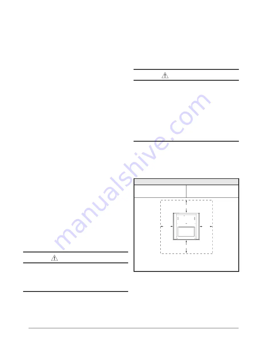
• The dimensions of the room or alcove must be able to 

accommodate the overall size of the unit and the installation 

clearances listed in 

Table 1

Physical dimensions for this 

air handler are also shown in 

Figure 8 (page 14)

.

•  The air handler should be set into position before routing 

the refrigerant tubing.

Minimum Clearances

• This appliance must be installed in accordance with 

clearances listed in 

Table 1

The air handler must be 

installed with ample clearance for easy access to the air 

filter, blower assembly, heater assembly, controls, and 

vent connections. Applicable building codes may require 

additional clearance to equipment. Refer to applicable 

building codes for details.

• Static pressure drop through louvered openings and 

through return air plenums should be considered in the 

overall duct design in the determination of the total external 

static pressure.

Installation in a Garage

 WARNING:

Do not place combustible materials on or against 

the cabinet. Do not place flammable materials, 

(gasoline, paint thinners, etc.) or any other 

flammable vapors and liquids, in the vicinity of 

the air handler.

The B64 Series air handler may be installed in a residential 

garage with the provision that the unit must be located or 

protected to prevent physical damage by vehicles.

Plenums & Air Ducts

•  Plenums and air ducts should be installed in accordance 

with the standards of the National Fire Protection 

Association Standard for Installation of Air Conditioning 

Systems (NFPA 90A), Standard for Installation of Residence 

Type Warm Air Heating and Air Conditioning Systems (NFPA 

90B), and all applicable local codes. NFPA publications 

are available by writing to: National Fire Protection 

Association, Batterymarch Park, Quincy, ME 02269 or visit  
www.NFPA.org online.

 WARNING:

All return ducts must be secured to the air 

handler using appropriate methods. All return 

ducts must be adequately sealed. When return 

air is provided through the bottom of the unit, 

the joint between the air handler and the return 

air plenum must be air tight.
Return air and circulating air ducts must not be 

connected to any other heat producing device 

such as a fireplace insert, stove, etc. This may 

result in fire, explosion, carbon monoxide 

poisoning, personal injury, or property damage.

• Design the duct work according to methods described 

by the Air Conditioning Contractors of America (ACCA).

•  This unit is designed only for use with a return and supply 

duct. The return air duct must have the same free area as 

the opening provided on the air handler. The ducts should 

be appropriately sized to the capacity of the air handler 

to ensure its proper airflow rating.

INSTALLATION CLEARANCES

Left Side ............. 0 Inches

Right Side ......... 0 Inches

Back ................. 0 Inches

Front ...............†See Notes


NOTE:

Alcove Installations

 - Allow 24 in. minimum clearance from front 

of unit to nearest wall or partition for servicing. Recommended 

clearance is 36 in.

REAR

RIGHT

SIDE

LEFT
SIDE

FRONT

Table 1. Minimum Unit Clearances

Содержание B64EM Series

Страница 1: ...well Pay attention to all safety warnings and any other special notes highlighted in the manual Improper installation of the furnace or failure to follow safety warnings could result in serious injury...

Страница 2: ...wer Continuously 11 Selecting Continuous Low Speed Fan Operation 11 Turning the Blower Off 11 System Cooling 11 System Heating 11 Selecting Minimum Electric Heat Airflow 11 Blower Configurations 11 De...

Страница 3: ...ation service and operation of this unit Unqualified individuals should not attempt to interpret these instructions or install this equipment Failure to follow safety recommendations could result in p...

Страница 4: ...ment Refer to applicable building codes for details Static pressure drop through louvered openings and through return air plenums should be considered in the overallductdesigninthedeterminationoftheto...

Страница 5: ...needed gaskets and grommets around penetrations into the air handler such as for electrical wiring AIR HANDLER INSTALLATION B64 series air handlers are shipped ready for vertical upflow installation a...

Страница 6: ...Right Installations 1 Remove the coil access door Unscrew the line set tube close off plate from the front left cabinet rail 2 Slide the coil and drain pan assembly out of the unit 3 Remove the sheet...

Страница 7: ...ntact with valve when gas is escaping Always ensure adequate ventilation is present during the depressurization process Address any uncertainties before proceeding Failure to comply with this warning...

Страница 8: ...ondensables to prevent low efficiency operation or damage to the unit The suggested range of evacuation is 350 500 microns 9 Charge the system with refrigerant Refer to the outdoor unitinstallationman...

Страница 9: ...ation service and operation of this unit Unqualified individuals should not attempt to interpret these instructions or install this equipment Failure to follow safety recommendations could result in p...

Страница 10: ...5 Connect blue blower limit wires according to Heater Kit Installation Instructions and the corresponding Wiring Diagram If a heater kit is not installed 1 Remove the 2 wire plug of the air handler b...

Страница 11: ...n B64EM models B64VM models automatically set the heating speed based on the amount of installed heat The A B switch must be set appropriately for the unit cabinet size For C sized cabinets the A B sw...

Страница 12: ...cted airflow while the system is in the lo cool mode and 100 of the selected airflow while in hi cool mode Units with an FSHE control scheme B64EM have a control board that includes a 7 segment displa...

Страница 13: ...or on the blower and motor as part of the annual inspection Blower Fan Wheel Inspect the blower wheel blades for accumulations of dirt and clean if necessary Inspect mounting nut for tightness when do...

Страница 14: ...typ 13 4 K O typ 1 7 8 3 5 8 5 5 8 DETAIL D 3 1 4 2 1 4 15 1 4 13 SUCTION LIQUID W 1 1 8 1 7 8 7 8 K O H 22 A CABINET SIZE H W A DETAIL D A 43 5 16 14 3 16 12 3 4 No B 43 5 16 19 11 16 18 1 4 No Tall...

Страница 15: ...l Drain Pan Coil Assembly Motor Mount Kit Blower Motor Transformer Capacitor Circuit Breaker 60A Heating Element Assembly Filter Tracks Blower Wheel Blower Housing Motor Control Board Filter Door Uppe...

Страница 16: ...0 795 720 685 0 1 1 0 1095 1040 995 950 900 850 805 750 1 1 1 0 1155 1105 1060 1010 965 920 870 825 0 0 0 1 1230 1185 1140 1090 1045 1010 965 920 1 0 0 1 1285 1260 1210 1165 1125 1080 1040 1010 0 1 0...

Страница 17: ...TON 560 560 1200 3 5 TON 600 600 1250 625 650 2 TON 1300 4 TON 700 2 TON 700 1350 750 750 1400 800 2 5 TON 800 2 5 TON 1450 850 850 1500 875 875 1550 890 950 1600 5 TON 930 1050 3 TON 1650 950 1150 3...

Страница 18: ...ING 0 OFF 1 ON AIRFLOW CFM 5 6 7 8 0 0 0 0 1100 0 0 0 1 1200 0 0 1 0 1250 0 0 1 1 1300 0 1 0 0 1350 0 1 0 1 1400 0 1 1 0 1450 0 1 1 1 1500 1 0 0 0 1550 1 0 0 1 1600 1 0 1 0 1650 1 0 1 1 1700 1 1 0 0 1...

Страница 19: ...W1 W2 EHEAT ON 5 KW Stage 1 Heat on instantly Heat blower on after 3 second delay 8 KW 10 KW Stage 1 Heat on instantly Heat blower on after 3 second delay Stage 2 Heat on after 5 seconds delay 15 KW...

Страница 20: ...fter 5 seconds delay 15 KW Stage 1 Heat on instantly Cool blower on after 3 second delay Stage 2 Heat on after 5 seconds delay Stage 3 Heat on after 30 seconds delay 20 KW Stage 1 Heat on instantly Co...

Страница 21: ...cal Heat Pump with 2 Stage Air Handler G R W2 C O Y1 Thermostat O Y1 R C G R W E Thermostat Y1 C Y1 W2 Typical 2 Stage Air Conditioner with 2 Stage Air Handler Typical 2 Stage Heat Pump with 2 Stage A...

Страница 22: ...1 BLWDTC BLWDTC_R HEAT COOL EAC L 1 L 2 P2 R C G W Y 3A Fuse HEATER P1 Figure 12 Single Stage Control Board C R G Y2 Y O 1W 2W 1Y L LED 1 HEATER P1 L 2 HUM EAC P2 3A Fuse P3 Figure 13 Two Stage Contro...

Страница 23: ...R ECM BLOWER Figure 14 Fixed Speed Motor Control Board GND SENSOR DEHUM Y1 H L2 OUT L2 IN L1 IN L1 OUT Y1 Y Y2 W C EXPANSION PORT R RED GREEN TEST PORT BLOWER MOTOR RED INPUTS COOL HEAT FAN SPEED OUTP...

Страница 24: ...entation avant l entretien 3 Le transformateur peut avoir un robinet principal double tension Agencez la position du robinet au type de tension de l installation 4 Si le c blage interne est remplac ut...

Страница 25: ...e tension Agencez la position du robinet au type de tension de l installation 4 Si le c blage interne est remplac utilisez seulement un fil de cuivre 105 C du m me gabarit WIRING DIAGRAM CONNECT TO W1...

Страница 26: ...tterthanyourcustomer This includes being able to install the product according to strict safety guidelines and instructing the customer on how to operate and maintain the equipment for the life of the...

Страница 27: ...27...

Страница 28: ...10436960 NEW Specifications illustrations subject to change without notice or incurring obligations 08 22 O Fallon MO Nortek Global HVAC LLC 2022 All Rights Reserved...

Отзывы: