CONFIDENTIAL AND PROPRIETARY
©Norsat International Incorporated (“Norsat”) All Rights
Reserved
2021-02-16 INS001201 Rev B
13
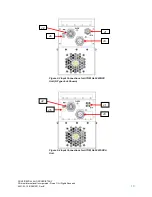
2.3.2 DC Unit J3 Connector Pinouts
Figure 2-7: DC Unit J3 Connector Pinout
Table 2-1: DC Unit J3 Connector Pinout
Pin
Name
A
V-/Ground
B
V+
C
V+
D
V-/Ground
For the DC input, the positive terminals are pins B/C and the negative terminals are pins A/D. Pins A and
D are connected to case ground internally; pins B and C are connected together internally. It is
recommended to apply the supply voltage evenly to both pairs of pins to evenly share the current among
both sets of wires/pins.
The internal capacitance between the V+ and V- terminals is approximately 120 microfarads.
2.4 J2
–
Monitor and Control Interface
The M&C interface is used to control the unit with a host computer. All on-board sensors are accessed
through this interface. Use of this connection is optional. Each ATOM is supplied with a mating connector
for the M&C interface.
The 25-50W ATOM can be ordered with standard or Ethernet web interface options. Table 2-2 summarizes
the M&C interface protocols available with each option.
A
B
D
C
Содержание ATOM-100060
Страница 1: ...1 USER MANUAL ATOM Ka 25 40W 50W BUC SSPA ...

