6
7
Installation
Before installation the operating conditions of temperature, pressure, etc. must be checked for
conformity with the Technical Data.
The unit should be mounted securely in an accessible and visible location upstream from lubricators and
near components being served. Strain on pipe work and fittings should be avoided and directional flow
arrows observed. With cyclic demand systems the filterregulator should be installed upstream of
directional control valves. Airline piping should be the same size as unit ports with airflow in the
direction of the arrow.
A pressure gauge may be connected to the appropriate R
c
1/8 port after removing the plug and should
have a range exceeding the maximum proposed outlet setting.
Adjustment
With the regulator adjustment completely backed-off the air supply can be turned on. The adjusting knob
can be rotated clockwise to increase the spring load and the pressure increase observed on the gauge.
Minor adjustments after setting changes can be avoided by always approaching the desired setting
from a lower level. When a lower setting is required, firstly reduce to a lower level and secondly increase
to the desired setting.
Decreasing the pressure setting on a relieving type regulator will cause air to exhaust through the
bonnet vent hole.
The non rising adjusting knob includes a locking feature; push knob in after setting to lock and prevent
adjustment. To release pull knob out.
Auto-drain units should have a 4 mm bore flexible tube pushed in the M5 quick-coupler on the bottom
of the bowl to pipe away expelled condensate.
Avoid restricting the drain pipe. Manual drain units must be drained before the contaminant level reaches
the element. Should this occur then liquid contaminant will be carried downstream.
Maintenance
Air service equipment should be initially maintained annually. Use, quality of air and condition at
examination may indicate adjustment of the maintenance interval.
Before attempting to service any unit, shut-off the air supply and exhaust the system completely.
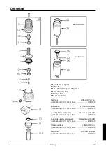
Unscrew the filter bowl (25) counter-clockwise and remove with O-ring (26). Unscrew the element (11a)
and remove complete with louvre (11) and gasket (10).
The bowl should be cleaned using soapy water ONLY. (Solvents, etc. can damage or destroy seals, etc.)
Bowls should be inspected for signs of mechanical damage corrosion.
Partial cleaning of the filter element is possible by washing the element in soapy water and blowing out
thoroughly with compressed air. Replacement by a clean element is recommended.
To disassemble the regulator section turn the adjusting knob (1b) counter-clockwise to relieve compres-
sion on the adjusting spring (2). The bonnet assembly (1a) can be removed by unscrewing and
enables removal of the adjusting spring (2), slip ring (3) and diaphragm (4). Unscrew the valve seat (5b)
and remove with 0-ring (5c). Valve (6) and spring (7) may then be removed.
Inspect all components for damage, foreign matter and cleanliness and reassemble using service
replacement parts where necessary. During reassembly all 0-rings, gaskets and where applicable, the lip
of the auto drain valve, should be lightly smeared with BPLS2 Energrease (or similar) and the diaphragm
valve pin checked for free movement in the valve seat.
The manual drain should be drained weekly and the filter element changed annually.
The regulator should be assembled in the vertical position. Tighten the valve seat (5b) to 0.4 to 0.7 Nm,
the element (11a) and bowl (25) to 0.5 to 1.0 Nm and the bonnet (1a) to 7 to 8 Nm.
Warning
Disposal of non metallic materials must be carried out in an approved manner. Burning may generate
toxic fumes.
For use in compressed air systems only. Not to be used where pressures and temperatures can exceed
those listed under Technical Data.
Downstream equipment that could malfunction or be damaged by pressure in excess of the regulated
pressure must be protected by a pressure relief device. This device must satisfy the system requirements
for pressure setting and flow capacity and be installed between the regulator and downstream equip-
ment. Where pressure gauge inaccuracies may be hazardous to personnel or property they should be
checked/calibrated before installation and regularly during use.
Warranty
For warranty details please refer to the "General Conditions of Sale"
Installation and maintenance instructions
GB

