background image

7

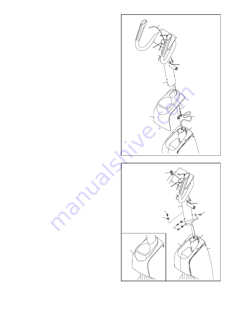
3. Orient the Upright (5) and the Top Cover (27) as

shown, and slide the Top Cover upward onto

the Upright.

Have a second person hold the Upright (5) and

the Top Cover (27) near the Main Frame (1).

Locate the wire tie in the Upright (5). Tie the

lower end of the wire tie to the Wire Harness

(60). Next, pull the upper end of the wire tie

until the Wire Harness is routed completely

through the Upright.

Tip: To prevent the Wire Harness (60) from

falling into the Upright (5), secure the Wire

Harness with the wire tie.

4. Note: For clarity, the Top Cover (27) is not

shown in this step.

Tip: Avoid pinching the Wire Harness (60).

Slide the Upright (5) onto the Main Frame (1).

Attach the Upright (5) with four M8 x 16mm

Patch Screws (102) and four M8 Split Washers

(103);

do not tighten the Patch Screws yet.

See the inset drawing.

Slide the Top Cover

(27) downward;

do not press the Top Cover

onto the Frame Covers (21, 22) yet.

3

Wire Tie

Wire Tie

5

27

60

1

4

5

103

103

102

102

102

22

21

27

Avoid pinching the

Wire Harness (60)

60

1

Содержание E 12.0 NTEVEL81210.0

Страница 1: ...erial number in the space above for reference www iconeurope com QUESTIONS If you have questions or if there are missing parts please contact us UK Call 08457 089 009 From Ireland 053 92 36102 Website...

Страница 2: ...DED DRAWING 29 ORDERING REPLACEMENT PARTS Back Cover RECYCLING INFORMATION Back Cover WARNING DECAL PLACEMENT 2 NordicTrack is a registered trademark of ICON IP Inc This drawing shows the location s o...

Страница 3: ...e elliptical and 2 ft 0 6 m on each side To protect the floor or carpet from damage place a mat under the elliptical 7 Inspect and properly tighten all parts regularly Replace any worn parts immediate...

Страница 4: ...ver of this manual To help us assist you note the product model number and serial number before contacting us The model number and the location of the serial number decal are shown on the front cover...

Страница 5: ...embly The number in parentheses below each drawing is the key number of the part from the PART LIST near the end of this manual The number following the key number is the quantity needed for assembly...

Страница 6: ...the Rear Stabilizer 4 press the Latch Button 67 and unfold the elliptical so that the Rear Stabilizer is resting on the floor 1 2 Orient the Front Stabilizer 3 so that the small welded tubes are faci...

Страница 7: ...To prevent the Wire Harness 60 from falling into the Upright 5 secure the Wire Harness with the wire tie 4 Note For clarity the Top Cover 27 is not shown in this step Tip Avoid pinching the Wire Harne...

Страница 8: ...t Axle 6 Identify the Right and Left Upper Body Legs 6 7 which are marked with Right and Left stickers and orient them as shown Slide the Right and Left Upper Body Legs 6 7 onto the right and left sid...

Страница 9: ...rient them as shown Attach the Right Pedal 14 to the Right Pedal Arm 12 with three M8 x 44mm Patch Screws 55 and three M8 Washers 95 do not tighten the Patch Screws yet Next tighten two M6 x 50mm Patc...

Страница 10: ...e right Crank Arm 39 Attach the Pedal Arm Sleeve 46 with an M8 x 25mm Patch Screw 121 a Large Axle Cover 113 and an M8 Washer 95 Next pull upward on the Latch 50 on the Right Pedal Arm 12 Press the Ri...

Страница 11: ...x 16mm Patch Screw 102 a Small Axle Cover 56 and an M8 Washer 95 into the other end of the Link Arm Axle Repeat this step on the other side of the elliptical 11 95 95 56 56 6 114 102 102 Grease Narro...

Страница 12: ...ties Connect the wires on the Console 33 to the Pulse Wire 105 the Wire Harness 60 and the Grip Wires 45 104 Make sure to connect the console wire that has a tag to the Grip Wire that has a tag Insert...

Страница 13: ...ptacle on the frame of the elliptical exer ciser Then attach the adapter to the power cord if necessary 24 25 5 16 17 Make sure that all parts of the elliptical are properly tightened Note Some hardwa...

Страница 14: ...warm dry place Do not store the chest pulse sensor in a plastic bag or other container that may trap moisture Do not expose the chest pulse sensor to direct sun light for extended periods of time or t...

Страница 15: ...lug the indicated end of the appropriate power cord into the receptacle on the elliptical 2 Plug the power cord into an appropriate out let that is properly installed and earthed in accordance with al...

Страница 16: ...the frame Next pull the pedal arms away from the handlebars Then lift the latches under the pedal arms and set the pedal arms on the pedal arm sleeves Release the latches and make sure that the pedal...

Страница 17: ...e direction To dismount the elliptical wait until the pedals come to a complete stop Note The elliptical does not have a free wheel the pedals will continue to move until the flywheel stops When the p...

Страница 18: ...amp and prompts you to vary your pedaling pace as it guides you through an effective workout The console also features an iFit training mode that allows your console to communicate with your wire less...

Страница 19: ...the pedals and the incline of the ramp as desired As you pedal change the resistance of the pedals by pressing one of the numbered 1 Step Resistance buttons or by pressing the 1 Step Resistance Incre...

Страница 20: ...for approxi mately ten seconds with your palms rest ing against the metal contacts Avoid moving your hands or gripping the contacts tightly When your pulse is detected your heart rate will appear in t...

Страница 21: ...t is divided into one minute seg ments One resistance level one ramp incline and one target rpm pedaling pace are programmed for each segment Note The same resistance level ramp incline and or target...

Страница 22: ...e ramp incline for the next segment The workout will continue in this way until the last segment ends To stop the workout at any time stop pedaling A tone will sound and the time will begin to flash i...

Страница 23: ...r make sure that the audio cable is fully plugged in Next press the play button on your MP3 player or CD player Adjust the volume level using the volume con trol on your MP3 player or CD player or pre...

Страница 24: ...The ramp cal ibration instructions will appear in the display Press the 1 Step Power Ramp Increase or Decrease button to calibrate the ramp The ramp will move upward and downward as it calibrates When...

Страница 25: ...ft the Left Pedal Arm off the left Pedal Arm Sleeve 46 Next remove the indicated M8 x 25mm Patch Screw 121 Large Axle Cover 113 M8 Washer 95 and Pedal Arm Sleeve 46 Using a flat screwdriver care fully...

Страница 26: ...your goal is to strengthen your cardiovascular system you must perform aerobic exercise which is activity that requires large amounts of oxygen for prolonged periods of time For aerobic exercise adju...

Страница 27: ...s 45 1 Right Grip Wire 46 2 Pedal Arm Sleeve 47 4 Large Bushing 48 1 Upright Axle 49 2 Latch Housing 50 2 Latch 51 2 Large Latch Spring 52 2 Latch Insert 53 4 Long Latch Spring 54 4 Leg Bearing Assemb...

Страница 28: ...28 2 Short C pin 129 2 8 x 1 2 Screw 130 1 Ramp 131 1 Ramp Cover 132 2 Ramp Bushing 133 1 Ramp Axle 134 1 Lift Motor 135 1 Lift Motor Stop 136 2 Ramp Roller 137 1 Roller Axle 138 1 Lift Arm 139 2 Lift...

Страница 29: ...95 121 95 127 106 49 51 52 50 53 40 50 51 52 49 106 127 53 30 31 95 102 121 95 44 9 7 102 103 103 102 102 103 25 105 104 45 56 144 58 58 58 58 58 15 11 128 13 113 47 30 31 47 46 95 112 112 111 62 62...

Страница 30: ...4 98 97 92 99 85 76 87 71 86 86 68 106 106 70 69 125 120 124 123 146 106 129 117 108 107 117 63 108 110 72 39 86 100 147 107 142 141 38 61 115 2 37 4 37 122 39 131 130 29 29 109 133 64 1 64 41 16 100...

Страница 31: ...31 EXPLODED DRAWING C Model No NTEVEL81210 0 R1110A 17 17 18 19 20 21 22 106 106 106 106 106 106 106 106 106 106 106 106 106 106 106 29 106 106 29 29 29 29...

Страница 32: ...rt s see the PART LIST and the EXPLODED DRAWING near the end of this manual RECYCLING INFORMATION This electronic product must not be disposed of in municipal waste To pre serve the environment this p...

Отзывы: