background image

13

OPERATION AND ADJUSTMENT

THE PRE-LUBRICATED WALKING BELT

Your treadmill features a walking belt coated with high-

performance lubricant.

IMPORTANT: Never apply sil-

icone spray or other substances to the walking

belt or the walking platform. Such substances will

deteriorate the walking belt and cause excessive

wear.

HOW TO PLUG IN THE POWER CORD

Your treadmill, like any other type of sophisticated

electronic equipment, can be seriously damaged by

sudden voltage changes in your homeʼs power.

Voltage surges, spikes, and noise interference can

result from weather conditions or from other appliances

being turned on or off.

To decrease the possibility of

your treadmill being damaged, always use a surge

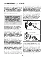
suppressor with your treadmill (see drawing 1 at

the right). To purchase a surge suppressor, see

your local NordicTrack dealer or call the telephone

number on the front cover of this manual and order

part number 146148, or see your local electronics

store.

Use only a single-outlet surge suppressor that is

UL 1449 listed as a transient voltage surge sup-

pressor (TVSS). The surge suppressor must have a

UL suppressed voltage rating of 400 volts or less

and a minimum surge dissipation of 450 joules.

The surge suppressor must be electrically rated for

120 volts AC and 15 amps. There must be a moni-

toring light on the surge suppressor to indicate

whether it is functioning properly. Failure to use a

properly functioning surge suppressor could result

in damage to the control system of the treadmill. If

the control system is damaged, the walking belt

may slow, accelerate, or stop unexpectedly, which

may result in a fall and serious injury.

This product must be grounded.

If it should malfunc-

tion or break down, grounding provides a path of least

resistance for electric current to reduce the risk of elec-

tric shock. This product is equipped with a cord having

an equipment-grounding conductor and a grounding

plug.

Plug the power cord into a surge suppressor,

and plug the surge suppressor into an appropriate

outlet that is properly installed and grounded in

accordance with all local codes and ordinances.

IMPORTANT: The treadmill is not compatible with

GFCI-equipped outlets.

This product is for use on a nominal 120-volt circuit,

and has a grounding plug that looks like the plug illus-

trated in drawing 1 below. A temporary adapter that

looks like the adapter illustrated in drawing 2 may be

used to connect the surge suppressor to a 2-pole

receptacle as shown in drawing 2 if a properly

grounded outlet is not available.

The temporary adapter should be used only until a

properly grounded outlet (drawing 1) can be installed

by a qualified electrician.

The green-colored rigid ear, lug, or the like extending

from the adapter must be connected to a permanent

ground such as a properly grounded outlet box cover.

Whenever the adapter is used it must be held in place

by a metal screw.

Some 2-pole receptacle outlet box

covers are not grounded. Contact a qualified elec-

trician to determine if the outlet box cover is

grounded before using an adapter.

DANGER:

Improper connection

of the equipment-grounding conductor can

result in an increased risk of electric shock.

Check with a qualified electrician or service-

man if you are in doubt as to whether the

product is properly grounded. Do not modify

the plug provided with the product—if it will

not fit the outlet, have a proper outlet

installed by a qualified electrician.

1

2

Grounded Outlet Box

Grounded Outlet Box

Grounding Plug

Surge Suppressor

Surge Suppressor

Grounding Pin

Adapter

Lug

Metal Screw

Grounded Outlet

Grounding Pin

Grounding Plug

Содержание CLUB REFLEX

Страница 1: ... above for reference www nordictrack com QUESTIONS If you have questions or if parts are damaged or missing DO NOT CON TACT THE STORE please contact Customer Care IMPORTANT Please register this product see the limited warranty on the back cover of this manual before contacting Customer Care CALL TOLL FREE 1 888 825 2588 Mon Fri 6 a m 6 p m MT Sat 8 a m 4 p m MT ON THE WEB www nordictrackservice co...

Страница 2: ...T 30 EXPLODED DRAWING 32 ORDERING REPLACEMENT PARTS Back Cover LIMITED WARRANTY Back Cover These drawings show the locations of the warning decals If a decal is missing or il legible call the telephone number on the front cover of this manual and request a free replacement decal Apply the decal in the location shown Note The decals may not be shown at actual size WARNING DECAL PLACEMENT 2 NordicTr...

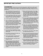
Страница 3: ...suppres sor not included and plug the surge sup pressor into a grounded circuit capable of carrying 15 or more amps No other appliance should be on the same circuit Do not use an extension cord 12 Use only a single outlet surge suppressor that meets all of the specifications described on page 13 To purchase a surge suppressor see your local NordicTrack dealer or call the telephone number on the fr...

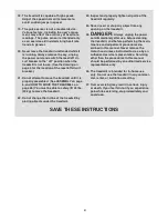
Страница 4: ...ble to safely lift 45 lbs 20 kg to move the treadmill 22 Do not change the incline of the treadmill by placing objects under the treadmill 23 Inspect and properly tighten all parts of the treadmill regularly 24 Never insert or drop any object into any opening on the treadmill 25 DANGER Always unplug the power cord immediately after use before cleaning the treadmill and before performing the main t...

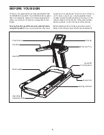
Страница 5: ...g this manual please see the front cover of this man ual To help us assist you note the product model number and serial number before contacting us The model number and the location of the serial number decal are shown on the front cover of this manual Before reading further please review the drawing below and familiarize yourself with the labeled parts BEFORE YOU BEGIN Handrail Console Key Clip R...

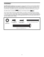
Страница 6: ...with a soft cloth and a mild non abrasive cleaner Assembly requires the included hex key and your own Phillips screwdriver Use the drawings below to identify the assembly hardware The number in parentheses below each drawing is the key number of the part from the PART LIST near the end of this manual The number after the parentheses is the quantity needed for assembly Note If a part is not in the ...

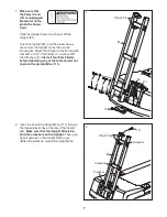
Страница 7: ...at the Power Cord 70 is unplugged Be careful not to pinch the Power Cord Slide the Upright Cover not shown off the Upright 81 Orient the Upright 81 and the plastic ties as shown Set the Upright on the tabs on the Frame 53 Attach the Upright to the Frame with four 3 8 x 3 1 4 Patch Bolts 1 and four 3 8 Star Washers 2 Start all four Patch Bolts before tightening any of them Be careful not to pinch t...

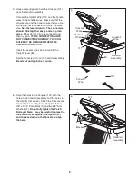
Страница 8: ...y Slide the bracket on the handrail assembly over the crossbar on the Upright 81 and set the handrail assembly on the Upright Be careful not to pinch any wires Handrail Assembly 4 3 Slide the Upright Cover 80 down onto the Upright 81 Be careful not to pinch the Upright Wire 111 Be careful not to hit the ceiling 111 80 3 81 81 Bracket 111 Crossbar ...

Страница 9: ...R IS TURNED ON Insert the excess wires downward into the Upright Cover 80 Set the Console 101 on the handrail assembly Be careful not to pinch any wires 80 101 111 5 Console Wires 111 Console Wire Handrail Assembly Handrail Wires Handrail Wire 6 Align the holes in the Console 101 with the holes in the handrail assembly and the holes in the Upright not shown Attach the Console and the handrail asse...

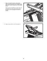
Страница 10: ...he Upright Cover 80 and sit inside the grooves on the Upright Cover Tighten two 6 x 5 8 Machine Screws 128 into the Upright Cover 80 in the locations shown Be careful not to overtighten the Machine Screws Teeth 80 1 102 8 Tighten the two 3 8 x 3 1 4 Patch Bolts 1 8 7 128 128 ...

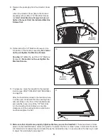
Страница 11: ... remove the plastic To protect the floor or carpet place a mat under the tread mill Note Extra hardware may be included Keep the included hex key in a secure place the hex key is used to adjust the walking belt see page 27 36 10 Tighten two 8 x 1 2 Machine Screws 4 into the bottom of the handrail assembly Be careful not to overtighten the Machine Screws See step 9 Tighten the six 8 x 2 1 4 Machine...

Страница 12: ... sensor in a plastic bag or other container that may trap moisture Do not expose the chest pulse sensor to direct sun light for extended periods of time do not expose it to temperatures above 120 F 50 C or below 15 F 10 C Do not excessively bend or stretch the sensor unit when using or storing the chest pulse sensor Clean the sensor unit using a damp cloth never use alcohol abrasives or chemicals ...

Страница 13: ... break down grounding provides a path of least resistance for electric current to reduce the risk of elec tric shock This product is equipped with a cord having an equipment grounding conductor and a grounding plug Plug the power cord into a surge suppressor and plug the surge suppressor into an appropriate outlet that is properly installed and grounded in accordance with all local codes and ordin...

Страница 14: ...fitness test workouts measure your fitness level or your VO2 max The console also features the new iFit interactive work out system The iFit system is compatible with iFit inter active workout cards containing workouts designed to help you achieve specific fitness goals For example lose unwanted pounds with the iFit Weight Loss work out or train for a long distance run with the iFit Marathon worko...

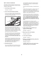
Страница 15: ... distance in either miles or kilometers For simplicity all instruc tions in this section refer to miles HOW TO USE THE MANUAL MODE 1 Insert the key into the console See HOW TO TURN ON THE POWER at the left The incline will automatically rise the maximum in cline level and then return to the minimum incline level 2 Select the manual mode Each time the key is inserted the manual mode will be selecte...

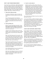
Страница 16: ... running pace in minutes per mile or minutes per kilometer Regardless of which display mode you select the speed or incline setting will appear in the display for a few seconds each time you change the set ting The lower right and lower left displays will show the speed of the walking belt and incline of the tread mill As you switch between workouts and the manual mode the console will keep track ...

Страница 17: ...page 15 2 Select one of the personal trainer workouts To select a per sonal trainer work out press the Interval button the Terrain button or the Random button repeatedly until the name of the desired workout appears in the display Interval workouts use speed settings to provide a personalized workout Terrain workouts use speed and incline settings to simulate an actual walking experience Random wo...

Страница 18: ... to a stop If the speed or incline setting is too high or too low at any time during the workout you can manually override the setting by pressing the Speed or Incline buttons however when the next segment of the workout begins the treadmill will auto matically adjust to the speed and incline set tings for the next segment Note If you use an Interval workout the incline will not adjust automat ica...

Страница 19: ...try work outs you must also enter your distance goal To use a manual control workout enter your time dis tance or calorie goal 3 Start the walking belt Press the Start Stop button to start the workout A moment after you press the button the treadmill will begin moving Hold the handrails and begin walking During the workout the profile will show the speed of the walking belt As you exercise change ...

Страница 20: ...button after each selection Note To use the Ebbeling Fitness Test you must also enter your gender 4 Start the walking belt Press the Start Stop button to start the workout A moment after you press the button the treadmill will automatically adjust to the first speed and incline settings of the fitness test Begin walking on the treadmill Note For the most accurate results do not hold the handrails ...

Страница 21: ... one minute segments One target heart rate setting is programmed for each segment The same target heart rate setting may be programmed for consec utive segments For a shorter workout simply stop the workout before it ends During all heart rate workouts the console will reg ularly compare your heart rate to the target heart rate setting If your heart rate is too far below or above the target heart ...

Страница 22: ...The height of the flashing segment indicates the incline setting for the current segment At the end of each segment a series of tones will sound and the next segment of the pro file will begin to flash If a new speed or incline set ting is programmed for the next segment of the workout the speed or incline setting will appear at the top of the display for a few moments to alert you The workout wil...

Страница 23: ...ill will automatically adjust to the first speed and in cline settings of the workout Hold the handrails and begin walking A personal trainer will guide you through the work out At the end of each segment a series of tones will sound If a new speed or incline setting is pro grammed for the next segment of the workout the speed or incline setting will appear at the top of the display for a few mome...

Страница 24: ...move to the next screen You may be able to select one of five lan guages for the displays If desired select a lan guage for the displays 3 Create a custom workout If desired create a custom workout Press the Display button until the desired custom workout is highlighted Then press the Enter button Program a speed setting and an incline setting for the first one minute segment by pressing the Speed...

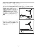
Страница 25: ...of injury do not lift the tread mill by the handrail Carefully roll the treadmill on the wheels to the desired location and then lower it to the level position CAUTION To reduce the risk of injury use extreme caution while moving the treadmill Do not attempt to move the treadmill over uneven sur faces After the treadmill is placed in the location where it will be used make sure that the leveling f...

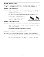
Страница 26: ...and then press the switch to the reset position PROBLEM The power turns off during use SOLUTION a Check the reset off circuit breaker see the drawing above If the circuit breaker has tripped wait for five minutes and then press the switch to the reset position b Make sure that the power cord is plugged in If the power cord is plugged in unplug it wait for five minutes and then plug it back in c Re...

Страница 27: ... center or slips when walked on SOLUTION a If the walking belt is off center remove the key and UNPLUG THE POWER CORD If the walking belt has shifted to the left use the hex key to turn the left idler roller bolt clockwise 1 2 of a turn if the walk ing belt has shifted to the right turn the left idler roller bolt counterclockwise 1 2 of a turn Be careful not to overtighten the walking belt Plug in...

Страница 28: ...e If your goal is to strengthen your cardiovascular system you must perform aerobic exer cise which is activity that requires large amounts of oxygen for prolonged periods of time For aerobic ex ercise adjust the intensity of your exercise until your heart rate is near the highest number in your training zone WORKOUT GUIDELINES Warming Up Start with 5 to 10 minutes of stretching and light exercise...

Страница 29: ...hilles Stretch With one leg in front of the other reach forward and place your hands against a wall Keep your back leg straight and your back foot flat on the floor Bend your front leg lean forward and move your hips toward the wall Hold for 15 counts then relax Repeat 3 times for each leg To cause further stretching of the achilles tendons bend your back leg as well Stretches Calves achilles tend...

Страница 30: ...h Stand Off 43 2 Rear Platform Bracket Cover 44 1 Walking Platform 45 2 Belt Guide 46 1 Walking Belt 47 1 Rear Platform Bracket 48 1 Front Platform Bracket 49 2 Platform Cushion 50 1 Magnet 51 1 Reed Switch 52 1 Controller 53 1 Frame 54 1 Drive Motor 55 4 Motor Bushing 56 1 Motor Mounting Plate 57 1 Motor Belt 58 1 Left Rear Cap Insert 59 1 Rear Cap 60 2 Cap Insert Bracket 61 1 Right Rear Cap Inse...

Страница 31: ...el Axle 119 2 Caution Decal 120 1 Voltage Warning Decal 121 2 English Warning Decal 122 1 Static Warning Decal 123 1 Motor Bracket 124 2 5 16 x 3 8 Washer Head Bolt 125 1 4 Console Ground Wire 126 1 8 Wire Tie 127 4 Platform Bracket Bushing 128 2 6 x 5 8 Machine Screws 129 4 Wheel Bushing 130 4 Flat Wheel Bushing 131 2 Lift Motor Washer 4 Red Wire M F 4 Blue Wire M F 4 Black Wire M F 18 White Wire...

Страница 32: ...2 37 38 38 41 43 45 12 12 48 44 46 47 113 20 51 50 52 54 57 56 59 25 37 58 61 64 17 60 64 25 41 60 17 17 63 53 49 62 22 22 36 36 55 55 42 34 34 34 34 34 34 23 24 24 62 89 43 45 65 112 124 117 119 119 120 89 127 127 123 49 10 114 114 23 100 EXPLODED DRAWING A Model No NTL29008 0 R1209A ...

Страница 33: ... 17 23 23 23 23 24 24 34 34 66 67 17 69 68 70 71 72 74 16 73 74 16 75 17 76 78 79 79 23 30 30 30 30 24 24 17 37 37 17 17 115 115 35 35 122 118 77 129 130 129 130 118 77 129 130 129 130 131 131 EXPLODED DRAWING B Model No NTL29008 0 R1209A ...

Страница 34: ... 116 85 24 92 91 90 86 87 88 25 93 94 95 84 24 83 82 80 18 3 81 3 18 18 3 26 26 26 30 30 25 25 25 23 19 19 19 19 19 4 4 3 25 96 111 116 116 121 121 126 128 128 87 25 25 EXPLODED DRAWING C Model No NTL29008 0 R1209A 34 ...

Страница 35: ... 28 28 28 28 26 26 23 27 27 107 101 106 102 99 97 98 25 25 25 25 24 1 1 23 23 24 24 24 2 2 25 25 29 39 40 40 103 104 105 24 24 106 108 109 110 125 23 23 23 23 EXPLODED DRAWING D Model No NTL29008 0 R1209A ...

Страница 36: ...ip charge This warranty does not extend to any damage to a product caused by or attributable to freight damage abuse misuse improper or abnormal usage or repairs not provided by an ICON authorized service cen ter to products used for commercial or rental purposes or as store display models or to products trans ported or purchased outside the US No other warranty beyond that specifically set forth ...

Отзывы: