


18
8
Module Installation
An optional module mounting bracket kit is available for purchase from NORAC. The
mounting brackets are compatible with control modules and input modules. One kit is needed
per module.
Item
Part Number
Name
Quantity
B20
43708
UC5 MOUNTING BRACKET KIT (CONTROL AND INPUT MODULES)
1
8.1
Control Module
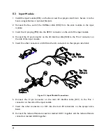
1.
Refer to
Figure 1
and
Figure 18
.
2.
Securely mount the control module (E01) inside the sprayer cab using screws, cable ties or
optional brackets.
3.
Connect the display terminal to the control module using the display cable. This cable must
be connected to the end of the control module with only one Deutsch connector.
4.
Connect the power cable (C30) to one of the two CANbus connectors on the control
module. Connect the other end of the power cable to a power outlet.
5.
Route cable C01 from the other CANbus connector towards the rear of the sprayer.
Figure 18: Control Module Mounting
Содержание UC5 Sx275
Страница 1: ...Versatile Sx275 Installation Manual VS01 ...
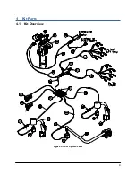
Страница 7: ...4 4 Kit Parts 4 1 Kit Overview Figure 2 VS01 System Parts ...
Страница 8: ...5 4 2 Hydraulic Plumbing Figure 3 VS01 Hydraulic Plumbing ...
Страница 31: ...28 12 3 ITEM C03 43210 03 CABLE UC5 NETWORK 18 AWG 3M 12 4 ITEM C04 43210 01 CABLE UC5 NETWORK 18 AWG 1M ...
Страница 32: ...29 12 5 ITEM C05 43210 20 CABLE UC5 NETWORK 18 AWG 20M 12 6 ITEM C10 43230 04 CABLE UC5 VALVE DT TO DT ...
Страница 33: ...30 12 7 ITEM C20 43240 01 CABLE UC5 INTERFACE TILT DT ...
Страница 34: ...31 12 8 ITEM C21 43240 07 CABLE UC5 INTERFACE MAIN DT WITH AUX 1 2 ...
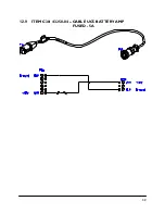
Страница 35: ...32 12 9 ITEM C30 43250 04 CABLE UC5 BATTERY AMP FUSED 5A ...


