


Chapter 5: Connecting to the Network
96
IP700 Series Installation Guide
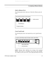
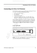
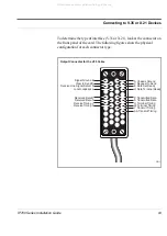
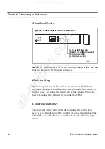
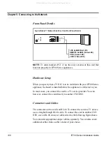
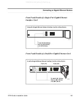
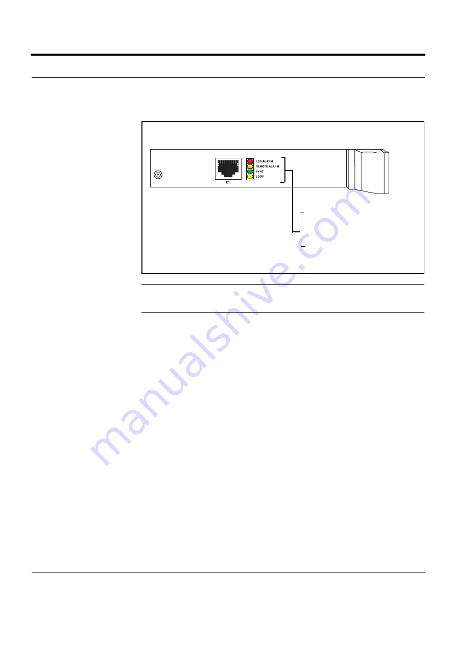
Front Panel Details
NOTE:
E1 cards marked
cPCI v2
are the only versions of this card that
function properly in IP700 Series appliances.
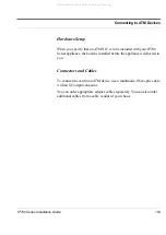
Hardware Setup
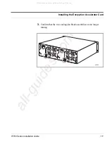
When you specify that an E1 card is to be part of your IP700 Series
appliance, the board is installed before the appliance is delivered to you.
In most cases, you connect the card to a E1 service provider. You can,
however, connect the card directly to another CSU/DSU.
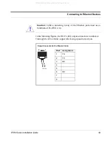
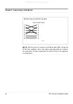
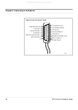
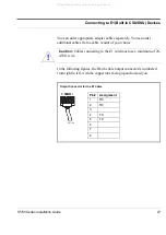
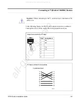
Connectors and Cables
The connector on the card is an RJ-48. To connect the card to an E1
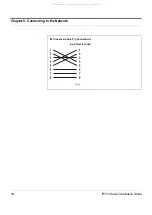
service, use a straight-through RJ-48 cable. To connect the card to another
CSU/DSU, use an RJ-48 crossover cable wired as the following figure
shows.
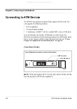
Typical E1 Network Interface Card Front Panel Details
E1-120
CPCIv2
00181
LOS ALARM (Red LED)
REMOTE ALARM (Yellow LED)
SYNC (Green LED)
LOOP (Yellow LED)
All manuals and user guides at all-guides.com
all-guides.com
Содержание IP710 Series
Страница 4: ...All manuals and user guides at all guides com ...
Страница 10: ...10 IP700 Series Installation Guide Figures All manuals and user guides at all guides com ...
Страница 18: ...About This Guide 18 IP700 Series Installation Guide All manuals and user guides at all guides com ...
Страница 108: ...Chapter 5 Connecting to the Network 108 IP700 Series Installation Guide All manuals and user guides at all guides com ...
Страница 152: ...Chapter 9 Using tcpdump 152 IP700 Series Installation Guide All manuals and user guides at all guides com ...
Страница 158: ...Appendix A Technical Specifications 158 IP700 Series Installation Guide All manuals and user guides at all guides com ...
Страница 182: ...Index 182 IP700 Series Installation Guide All manuals and user guides at all guides com ...


