


IP700 Series Installation Guide
101
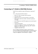
Connecting to T1 (Built-in CSU/DSU) Devices
Caution:
Cables connecting to the T1 card must use a minimum of 26-
AWG wire.
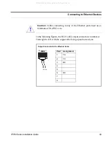
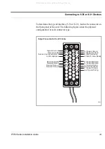
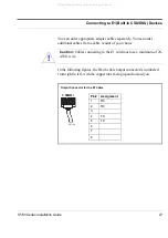
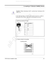
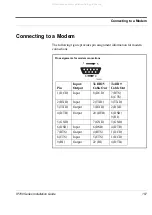
In the following figures, the RJ-48 cable output connector is numbered
from right to left, with the copper tabs facing up and toward you.
!
00113b
Pin#
Assignment
1
RX
2
RX
3
4
TX
5
TX
6
7
8
8
1
Output Connector for the T1 Cable
00018
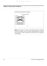
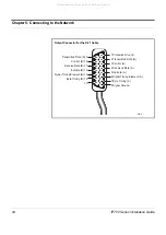
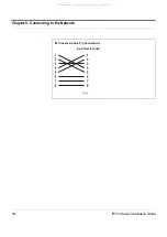
T1 Crossover Cable Pin Connections
8-pin female (host)
All manuals and user guides at all-guides.com
all-guides.com
Содержание IP710 Series
Страница 4: ...All manuals and user guides at all guides com ...
Страница 10: ...10 IP700 Series Installation Guide Figures All manuals and user guides at all guides com ...
Страница 18: ...About This Guide 18 IP700 Series Installation Guide All manuals and user guides at all guides com ...
Страница 108: ...Chapter 5 Connecting to the Network 108 IP700 Series Installation Guide All manuals and user guides at all guides com ...
Страница 152: ...Chapter 9 Using tcpdump 152 IP700 Series Installation Guide All manuals and user guides at all guides com ...
Страница 158: ...Appendix A Technical Specifications 158 IP700 Series Installation Guide All manuals and user guides at all guides com ...
Страница 182: ...Index 182 IP700 Series Installation Guide All manuals and user guides at all guides com ...


