Nitek EtherStretch ER8500C Скачать руководство пользователя страница 6

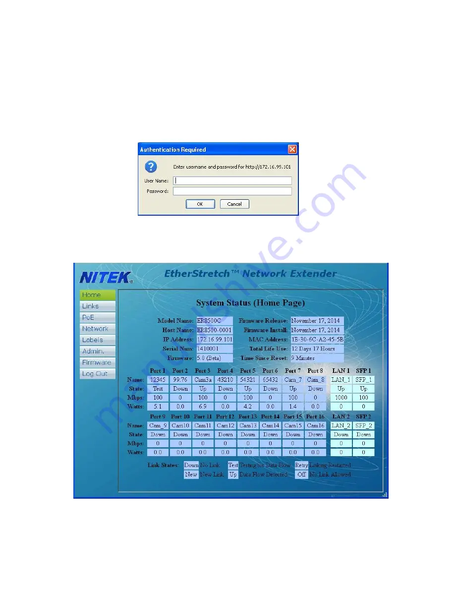
BROWSER BASED GUI – LOGIN PAGE 

 
The ER8500C and ER16500C do not require a user setup or configuration in order to function. When using a single unit. 
Multiple units do need to be configured to prevent IP address conflicts, which could occur. The Graphical User Interface 
(GUI) provide access to additional features to provide for monitoring of the system and customizing of the settings. 

 
In order to connect with the unit, connect an Ethernet port of a PC to any port of the ER8500/ER16500 unit. Go into the 
network setting for your PC and set its address to 

192.168.1.100

 and a subnet mask of 

255.255.255.0

. The default IP 

address of the ER unit is 

//192.168.1.1

, enter the address of 

//192.168.1.1 

into your Browser. The unit will display a login 

screen below. The default login is Name; “

admin

” with not password. 

After login you will come to the 

HOME

 screen shown below. The Home screen provides a look at some basic informa-

tion about your unit. From here you can see basic information about the status of each port, current firmware, IP ad-
dress, and MAC address among other things. There are no settings or controls on this page.  

Содержание EtherStretch ER8500C

Страница 1: ...any heat sources such as radiators heat registers stoves or other appara tus that produce heat Patent Pending USA and Europe Euro Pat App 2779641 NITEK De Aar 99 8253 PN Dronten The Netherlands Tel 31...

Страница 2: ...E the ambient temperature in a closed or multi unit rack assembly could greatly exceed the ambi ent temperature outside that assembly b Air Flow Leave space on the sides of the unit for airflow into t...

Страница 3: ...flashing slowly it will indicate that the network has a loop in it and data is cascading It is recommended to remove the second LAN jack if this occurs and see if the problem goes away The data speed...

Страница 4: ...n on followed by the LINK STATUS LED on the Network Port The IP camera or other Ethernet device should now be ready to operate Continue installing the remaining transmitters as needed Connector LED OF...

Страница 5: ...e maximum power available for your length of coax 11 If the needed level of power is not available for the length of coaxial cable alternate options are available One method is to directly power the t...

Страница 6: ...ort of the ER8500 ER16500 unit Go into the network setting for your PC and set its address to 192 168 1 100 and a subnet mask of 255 255 255 0 The default IP address of the ER unit is 192 168 1 1 ente...

Страница 7: ...onal rights Restricted will only allow this person to see the Home screen and the Log Out Screen POE On Off will allow a user to turn off power to individual transmitters and cameras and to make syste...

Страница 8: ...is from time to time updated to add fea tures to the unit These updates are mostly in the form of added features in this webpage section Firmware updates will be posted to the Nitek website at www ni...

Страница 9: ...perly setup This can lead to a false reading In this rare case Mode may need to be set to DM Discovery Mode to allow for cameras to be configured Once the cameras are properly configured the setting c...

Страница 10: ...each port at the ER8500C ER16500C end In this screen you can also turn on all of the POE ports or reset the whole unit is needed The Labels button takes you the screen where you can apply a custom la...

Отзывы: