Nitek EtherStretch ER8500C Скачать руководство пользователя страница 4

Transmitter-end Installation  
ET1500C or ET4500C Units 

 
6) At the camera location securely mount the transmitter. 


7) Find the coaxial cable from the head-end and make sure it is properly terminated RG59 or RG6 (75 ohm type) solid 

copper cable. Connect coaxial cable to the BNC jack of the transmitter. If the head-end unit is powered up it will 
sense the connection of the transmitter unit and turn on the power. This will be indicated by the green POWER LED 
on the “Network Port”. After about 15 to 30 seconds the green 10/100 (upper) LED at the “Coax Port” will turn-on to 
tell you that the head-end has connected with the transmitter unit. The Ethernet device does not need to be con-
nected for the transmitter to communicate with the head-end. 


8) Finally, connect an Ethernet device to the transmitter “Network Port”. If the device requires PoE power, the POE OUT 

(lower) LED at the “Coax Port” will turn on followed by the LINK STATUS LED on the “Network Port”. The IP camera 
or other Ethernet device should now be ready to operate. Continue installing the remaining transmitters as needed. 

Connector 

LED 

OFF 

ON 

FLASHING 

Network 

Port 

Power No 

power 

Power 

Good 


Link Status 

No Ethernet  

Link 

Ethernet Link 

Good 


Link 
Port 

PoE Out 

No PoE  

Power Out 

PoE Power 

Good 


10/100 

No Link 

100Mb 

10Mb 

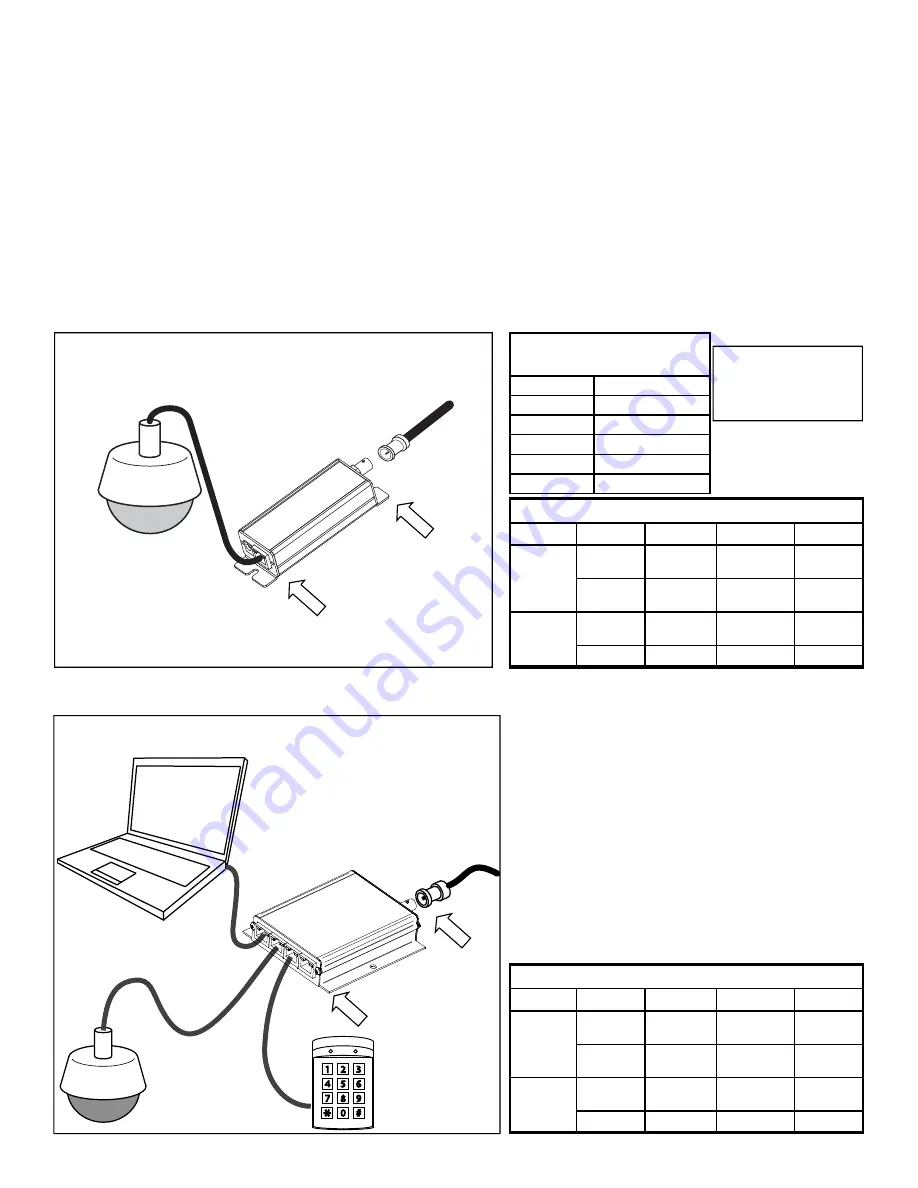
ET1500C LED INDICATORS 

ET1500

IP Camera 

Coax from 

Head-end 

Transmitter Hookup Diagram  

Link Port 

Network Port 

PoE Device Power 

RG59 Coax * 

Distance 

Power at PoE Port 

328ft/100m 21.7 

watts 

984ft/300m 18.2 

watts 

1312ft/400m 14.4 

watts 

1640ft/500m 12.2 

watts 

656ft/200m 21.7 

watts 

*

Results with ER8500 

Receiver and using RG59 
SBC Type Cable with 
20AWG Center


Connector 

LED 

OFF 

ON 

FLASHING 

Network 

Port 

PoE Out 

No PoE 

Power Out 

PoE Power 

Good 


Link Status 

No Ethernet  

Link 

Ethernet Link 

Good 


Link 
Port 

Power No 

Power 

Power 

Good 


10/100 

No Link 

100Mb 

10Mb 

ET4500C LED INDICATORS 

ET4

500

C

IP 1

IP 2

IP 3

IP 4

IP Camera 

Coax from 

Head-end 

4CH Transmitter Hookup Diagram  

Link Port 

4 Network Ports 

IP Device 

IP Device 

Содержание EtherStretch ER8500C

Страница 1: ...any heat sources such as radiators heat registers stoves or other appara tus that produce heat Patent Pending USA and Europe Euro Pat App 2779641 NITEK De Aar 99 8253 PN Dronten The Netherlands Tel 31...

Страница 2: ...E the ambient temperature in a closed or multi unit rack assembly could greatly exceed the ambi ent temperature outside that assembly b Air Flow Leave space on the sides of the unit for airflow into t...

Страница 3: ...flashing slowly it will indicate that the network has a loop in it and data is cascading It is recommended to remove the second LAN jack if this occurs and see if the problem goes away The data speed...

Страница 4: ...n on followed by the LINK STATUS LED on the Network Port The IP camera or other Ethernet device should now be ready to operate Continue installing the remaining transmitters as needed Connector LED OF...

Страница 5: ...e maximum power available for your length of coax 11 If the needed level of power is not available for the length of coaxial cable alternate options are available One method is to directly power the t...

Страница 6: ...ort of the ER8500 ER16500 unit Go into the network setting for your PC and set its address to 192 168 1 100 and a subnet mask of 255 255 255 0 The default IP address of the ER unit is 192 168 1 1 ente...

Страница 7: ...onal rights Restricted will only allow this person to see the Home screen and the Log Out Screen POE On Off will allow a user to turn off power to individual transmitters and cameras and to make syste...

Страница 8: ...is from time to time updated to add fea tures to the unit These updates are mostly in the form of added features in this webpage section Firmware updates will be posted to the Nitek website at www ni...

Страница 9: ...perly setup This can lead to a false reading In this rare case Mode may need to be set to DM Discovery Mode to allow for cameras to be configured Once the cameras are properly configured the setting c...

Страница 10: ...each port at the ER8500C ER16500C end In this screen you can also turn on all of the POE ports or reset the whole unit is needed The Labels button takes you the screen where you can apply a custom la...

Отзывы: