background image

 11 - FORM NO. 56041444 / SELECTSCRUB KA-27, KA-33, KA-39

____________________________________________________________________________________________________________________________________________________________________________________________________________________________________________________________________________________________

Please read and follow the “MAINTENANCE SCHEDULE” located under the recovery tank.
At the end of the day’s operation, the machine should be completely cleaned and prepared for the next shift’s operations. Careful maintenance will insure effective
performance throughout a long period of service.

____________________________________________________________________________________________________________________________________________________________________________________________________________________________________________________________________________________________

DRIVE MOTOR CHAIN ADJUSTMENT

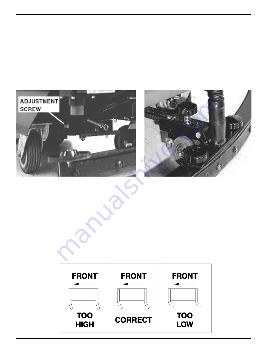
To adjust the tension of the chain, first loosen the adjustment screw’s jam nut (Figure 6). Next, turn the adjustment screw clockwise to tighten the chain and
counterclockwise to loosen. A properly adjusted chain should have a 1/2 inch of slack. When the chain is properly adjusted, retighten the jam nut.
NOTE: Excessive chain tension may cause damage to the bearings, sprockets, or chain.

MAINTENANCE

FIGURE 6

FIGURE 7

____________________________________________________________________________________________________________________________________________________________________________________________________________________________________________________________________________________________

SQUEEGEE TILT ADJUSTMENT

The squeegee on this machine pivots freely, allowing the pressure on each end of the squeegee to keep it level with the floor at all times. The front to rear tilt adjustment
is correct if, as the machine is moved forward, there is an equal amount of squeegee flare at the ends of the squeegee rubber compared to the center.
To adjust the tilt of the squeegee, turn the tilt adjustment screw which can be found on the squeegee bar just in front of the squeegee height adjustment knob (Figure
7). Turn the screw clockwise to tilt the ends of the squeegee upward and counterclockwise to turn the ends downward.

____________________________________________________________________________________________________________________________________________________________________________________________________________________________________________________________________________________________

SQUEEGEE HEIGHT ADJUSTMENT

In order for the squeegee to pick up effectively, the height must be adjusted to give the correct amount of squeegee rubber contact with the floor. If the squeegee
is too high or too low it will not pick up properly.
To adjust the height of the squeegee relative to the floor, turn the height adjustment knob (Figure 7) clockwise to lower the squeegee and increase pressure on the
squeegee blades. To raise the squeegee and reduce pressure on the squeegee blades, turn the knob counterclockwise to the desired height. Refer to Figure 8 for
the correct height adjustment for the squeegee.

FIGURE 8

Содержание SelectScrub KA-27

Страница 1: ...4 99 Form Number 56041444 083396 Kent SelectScrub KA 27 KA 33 KA 39 Models 56636998 56637002 56637005 OPERATOR M A N U A L...

Страница 2: ...MACHINE SPECIFICATIONS 2 3 ACCESSORIES 3 INTRODUCTION 4 IMPORTANT SAFETY INSTRUCTIONS 5 SET UP 6 OPERATION 7 CONTROLS 7 SOLUTION 8 CLEAN UP AND STORAGE 10 MAINTENANCE 11 BATTERY CHARGING 12 BATTERY C...

Страница 3: ...brushes All electronic control variable speed drive Featuring dynamic braking for easy control up and down ramps Dual 17 43 2cm dia self leveling counter rotating 195 rpm 33 83 8cm 125 lbs 56 7Kg 200...

Страница 4: ...mp Hr Single Battery Chargers 120 Volt 60 Hertz 100 Volt 50 Hertz 230 Volt 50 Hertz 230 Volt 60 Hertz Squeegee Blades Std Blade Set 3 Pcs Front Blade Std Rear Blade Backup Blade Neoprene Rear Blade 03...

Страница 5: ...x service sticker here _________________________________________________________________________________________________________________________________________________________________________________...

Страница 6: ...t you are cleaning When working with or near batteries always wear eye protection and protective clothing and remove all jewelry to prevent accidental electrical sparks and or shock Do not place tools...

Страница 7: ...TTERYWIRINGDIAGRAM locatedinsidethemachine just above the battery box Next install the brush covers Be sure to install the brush covers so that the latch is in the front of the machine Figure 1 SET UP...

Страница 8: ...____________________________________________________________________________________________________ DYNAMIC BRAKING Dynamic Braking built into the speed control helps to maintain a nearly constant sp...

Страница 9: ...___________________________________ RECOVERY TANK FLOAT SWITCH When water is detected at the full level the vacuum motor will automatically turn off until the recovery tank is emptied ________________...

Страница 10: ...ff to minimize residue buildup and odor OPERATION FIGURE 3 FIGURE 4 ____________________________________________________________________________________________________________________________________...

Страница 11: ...ly charged batteries Next add the correct ratio amount of the cleaning chemical to the solution tank Now fill the tank withwater agitatingitifpossible to2inchesbelowthebottomofthelidandinstallthebrush...

Страница 12: ..._________________________________________________________________________________________________________________________________________________________________________ SQUEEGEE TILT ADJUSTMENT Thesq...

Страница 13: ...ion electrolyte level up in cells Check daily if cells need water use only distilled or approved water 2 Keep batteries fully charged when not in use 3 Keep batteries and terminals clean When necessar...

Страница 14: ...________________________________________________________________________________________________________________________________________________________________________________________________________...

Страница 15: ...d hose entering recovery tank 1 Battery charge condition very low 2 Corroded wires or connectors SOLUTION 1 Turn keylock switch clockwise 2 Check BATTERY CONDITION meter and charge batteries 3 Adjust...

Страница 16: ...Nilfisk Advance Inc 14600 21st Avenue North Plymouth MN 55447 3408 www nilfisk advance com Phone 800 989 2235 Fax 800 989 6566 1999 Nilfisk Advance Inc Plymouth MN 55447 3408 Printed in the U S A...

Отзывы: