background image

FSA03601-R.3629.A

- A19

SB-600 -

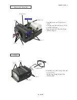
1m

Align the edges of the communication tool 

(J15405) and the stand (desk, etc).

Flash meter

PC

J15405

Standard reflector *

SB-600 does NOT have "Auto mode", so inspection and adjustment can be 

made without the standard reflector.  However, if there is something, etc that has 

extremely strong reflection in the background, it may affect the accuracy.  So it is 

recommended to use the standard reflector (J18360/J18069) as background.

Points to notice for Inspection & Adjustment of Flash

When the adjustment item 

3. Quantity of light adjustment

 is made, be careful of the following:

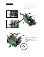
*Be sure to make the adjustment in a dark place (e.g. photo darkroom, etc) without influence of outside light.

*If there is some reflector (e.g. desk, etc) in front of SB, it may affect the accuracy.
Therefore, be sure to align both the edges of the communication tool (J15405) and stand (desk, etc) as shown below.

Содержание SB-600 FSA03601

Страница 1: ...FSA03601 R 3629 A 作成承認印 配布許可印 NIKON CORPORATION Tokyo Japan Printed in Japan November 2004 Copyright c 2004 by Nikon Corporation All Rights Reserved REPAIR MANUAL FSA03601 ...

Страница 2: ... D8 発光部 Lighting unit D8 D10 組立編 Assembly 発光部 Lighting unit A1 A2 モーター部 Motor unit A3 ZOOM 基板 Uケース ZOOM PCB U case A4 メインコンデンサ Main condenser A5 バウンスケースR Bounce case R A6 A7 バウンスケースF フレネルレンズ Lケース Bounce case F Fresnel lens L case A8 Rケース部組 R case unit A9 R基板 電池ケース部 R PCB Battery case unit A10 温度ヒューズ バッテリー基板 Thermal fuse Battery PCB A11 F基板 L基板 F PCB L PCB A12 電池ケース部とRケース部組の組立 Assemble Battery case...

Страница 3: ...justments are made A20 A22 調整ソフト J18365 Inspection adjustment software J18365 A23 フォーカシングライト点検 調整 Inspection adjustment of Focusing light A24 A25 電気編 Electricity 回路構成 Circuitry E1 E3 ブロック図 Block Diagram E4 EEPROM DATA E5 R基板 R PCB E6 F基板 L基板 F PCB L PCB E7 C基板 ZOOM 基板 脚基板 バウンス基板 XE A 基板 XE K 基板 C PCB ZOOM PCB FOOT PCB BOUNCE PCB XE A PCB XE K PCB E8 回路図 Circuit E9 実体配線図 Wiring E10 工具 TOOLS 工具 TOOL...

Страница 4: ...TTL mode Advanced Wireless Lighting FV Lock flash Flash color information communication Auto FP High Speed sync and Wide area AF Assist Illuminator Available multiple flash Usable camera Advanced Wireless Lighting Cameras compatible with CLS Multiple flash shooting using cords No limitation Slow sync Red eye reduction Red eye reduction in slow sync Rear curtain sync flash Auto FP High Speed sync F...

Страница 5: ...at M1 16 output 1 1600 sec at M1 2 output 1 20000 sec at M1 32 output 1 3400 sec at M1 4 output 1 25000 sec at 1 64 output 1 6600 sec at M1 8 output Provides secure attachment of SB 600 to casmera s accessory shoe using locking plate and mount pin to prevent accidental detachment 3 0 to 3 0 EV in increments of 1 3 steps in the TTL auto flash mode The following Custom Settings are possible Wireless...

Страница 6: ...ion OFF Zoom head position setting if the built in wide flash adapter is broken off accidentally OFF LCD panel illuminator ON Seting Custom Settings 1 Press the ZOOM and buttons simultaneously for approx 2 seconds to display the custom Settings mode 2 Press the or buttonto choose the desired custom settings 3 Press the ZOOM or MODE a button to display the preferred setting 4 Press the ZOOM and but...

Страница 7: ...ide Area AF Assist Illuminator Setting to activate or cancel the Wide Area AF Assist Illuminator AF ILL Activated NO AF ILL Canceled Standby function Setting the standby function to activate or cancel AUTO Standby function activated Standby function canceled Power zoom function Setting to activate or cancel the power zoom function which adjusts the zoom head position automatically OFF Activated ON...

Страница 8: ...te Lead free solder is used all for this product Side rubber PUSH 45 44 200Ω 2kΩ Remove right and left side rubbers Set the bounce angle to 90 and discharge the main condenser at the 2 holes of Fig 1 Leg unit Connector Black 234 4 Take out 4 screws 234 to remove the leg unit Unsolder the foot side of the black wire and remove the connector Then remove the leg unit from the body Leg unit Fig 1 44 4...

Страница 9: ...nit 224 2 Take out 2 screws 224 ref Fig 1 Open the battery lid Remove the F case unit then the battery lid comes off too Disconnect 2 connectors to detach the F case unit ref Fig 2 Battery lid F case unit Connector Fig 1 Fig 2 F case unit ...

Страница 10: ... for Fiber optics Fiber optics Remove 4 connectors that are connected from the head unit ref Fig 1 Remove the fiber optics ref Fig 2 Separate the head unit from the R case unit Fig 1 Fig 2 Head unit Insert the screw driver here to lift in the direction of arrow R case unit ...

Страница 11: ...from the R case unit Insulating plate Connector Connector F PCB L PCB 226 2 226 3 Wires red black F PCB L PCB 226 2 Take out 7 screws 226 and unsolder the L PCB to remove the red and black wires ref Fig 1 Detach the F PCB and L PCB at the same time from the battery case ref Fig 2 Fig 2 Fig 1 Battery case unit Battery case R case unit ...

Страница 12: ...e the F PCB and L PCB Battery PCB Thermal fuse 226 3 226 2 Solder Thermal fuse Battery PCB Take out 5 screws 226 and unsolder 2 parts of the thermal fuse Then detach the battery PCB from the battery box Note Unsolder the thermal fuse in a short time Otherwise it may be damaged R PCB 226 4 226 4 R PCB Take out 8 screws 226 to remove the R PCB ...

Страница 13: ...e wires Take out 2 screws 229 and 4 screws 231 to remove the L case L case Bounce case F Fresnel lens Fresnel lens 233 4 221 2 221 2 Ring Remove the fresnel lens Take out 4 screws 233 to remove the ring Take out 4 screws 221 to remove the bounce case F Case F Bounce case R 231 2 231 2 Take out 4 screws 231 ...

Страница 14: ...B 600 Detach the bounce case R from the U case Bounce case R U case Take out 4 screws 221 221 2 By removing the main condenser the parts can be disassembled as follows 221 2 Bounce case R 86 84 85 83 77 82 76 Main condenser ...

Страница 15: ... screws 230 and 2 screws 255 Solder Black orange Solder blue purple Unsolder the main condenser to remove blue and purple wires and the ZOOM PCB to remove black and orange wires to separate the ZOOM PCB from the motor unit ZOOM PCB Motor unit Lighting unit Lighting unit 72 68 Remove the E ring 72 Attached with glue Push the guide shaft 68 out in the direction indicated by the arrow and remove the ...

Страница 16: ...oks and zoom pressure shaft holder 59 55 53 Remove the glass retainer 55 to detach the glass panel 53 Soldered trigger coil 2 WHITE wires Xe A PCB Xe K PCB Unsolder the trigger coil to remove 2 white wires Unsolder the Xe tube at both ends to remove the Xe A PCB and Xe K PCB by using wicking wire Remove the Xe A PCB ...

Страница 17: ...the Xe A side of the Xe band 54 Pull out the Xe tube a little in the direction of the arrow and remove the Xe K PCB by pulling it in the direction of 54 Xe K PCB 54 WTRG2 97 57 56 71 XE701 The lighting unit can be disassembled as follows ...

Страница 18: ...the Xe band 54 to the A side of the X tube by following the arrow 54 Xe K PCB Assembly Lighting unit Attach the conductive tape 97 on the reflector 57 Solder the wire WTRG2 Attach the zoom brush 71 on the reflector holder 56 Attach the reflector 57 Note Check that the below 2 parts are hooked tightly Insert the Xe tube XE701 in the direction of the arrow 56 A side of Xe tube 97 57 WTRG2 WHITE 71 5...

Страница 19: ...e K PCB Attach the Xe A PCB to the Xe tube Solder the Xe A PCB Xe K PCB and Xe tube Solder 2 white wires of the trigger coil 55 Attach the glass retainer 55 Attach the glass panel 53 to the lighting unit while pressing it in the below direction Red part works as retainer 53 ...

Страница 20: ...wire of the Xe A PCB through under the Xe band 54 70 222 2 227 2 67 A B First put the A part of the zoom shaft 67 into the hole of the motor holder 69 then push the B part of it into 69 Solder 2 wires on the ZOOM motor 69 96 58 60 59 Hook Hook Insert the zoom pressure shaft holder 59 into the lighting unit and fix the 2 hooks as shown left Insert the spring 60 and zoom pressure shaft 58 Lighting u...

Страница 21: ...0 ZOOM PCB Solder wires on both sides of the ZOOM PCB Adhesive C8008B Adhesive EDA1021 U case GREEN RED BROWN BLACK ORANGE BLUE ORANGE WHITE BLUE GRAY GRAY GRAY PURPLE ZOOM PCB 51 49 50 2 48 43 SW601 223 41 92 81 61 64 64 202 2 ...

Страница 22: ...t to the left position then attach it with 2 screws 230 and 2 screws 255 Main condenser Solder 4 wires on the main condenser Solder 2 wires on the ZOOM PCB Fix the 4 wires that are connected from the main condenser with the tape TA 0002 ZOOM PCB Motor unit Tape TA 0002 PURPLE RED BLUE BLACK BLACK ORANGE ZOOM PCB U case Main condenser ...

Страница 23: ...ounce roller spring 79 on the click rotation axis 76 Put the wires through the center of the click rotation axis 79 U case Assemble so that A fits in the A hole and B fits in the B groove 76 52 2 90 89 88 34 203 87 86 221 4 82 83 77 Grease G7100 Grease G7100 Grease G7100 Bounce case R Bounce case R 79 78 Concave part Concave part ...

Страница 24: ... screws 231 85 84 Tape 87 Assemble the main condenser Note Assemble so that the convex parts of the bounce case R enters in the concave parts of the main condenser PCB Main condenser Convex parts of Bounce case R Main condenser PCB Concave part ...

Страница 25: ...ws 231 Pass the wires through the hole of the insulating plate L case Bounce case F Fresnel lens Fresnel lens 233 4 221 2 221 2 80 Attach the bounce case F with 4 screws 221 Attach the ring 80 with 4 screws 233 Attach the fresnel lens Apply the grease G7100 on the bounce roller moving part Bounce case F Grease G7100 ...

Страница 26: ...FSA03601 R 3629 A A9 SB 600 106 120 102 109 108 2 107 224 2 112 2 111 2 116 117 115 113 114 139 2 138 2 R case unit Assemble each part into the R case unit Convex parts ...

Страница 27: ...FSA03601 R 3629 A A10 SB 600 R PCB 226 4 226 4 R PCB Attach the R PCB with 8 screws 226 Battery case unit 143 144 146 2 145 2 121 Assemble the battery case unit ...

Страница 28: ...he thermal fuse as shown left by putting the terminals of the thermal fuse into the holes of the battery PCB Caution Using the adhesive other than TSE3941 may cause malfunction of the thermal fuse Use this adhesive only Solder the thermal fuse Caution Taking time to solder the thermal fuse may cause a damage to the thermal fuse Solder it in the shortest possible time Adhesive TSE3941 Terminals Bat...

Страница 29: ... NOT make soldering bridges of the F PCB and L PCB F PCB L PCB 226 2 226 3 F PCB L PCB 226 2 Attach the F PCB and L PCB with 7 screws 226 Solder 2 wires on the L PCB Make soldering bridges of the F PCB and L PCB ORANGE BLACK RED WHITE YELLOW BROWN ORANGE BLACK RED WHITE YELLOW BROWN F PCB L PCB Battery case Soldering bridges RED BLACK ...

Страница 30: ...ttery case unit and R case unit Connect 2 connectors and assemble the battery case unit into the R case unit Mount the insulating plate Insulating plate Connector Connector Position for attaching insulating plate Battery case unit R case unit ...

Страница 31: ...ching part Fiber optics Head unit A A B B C D C D Attaching part of fiber optics Fiber optics F case unit 103 235 3 132 134 135 WR5 101 Assemble each part into the F case unit Note In case the AF assist illuminating lamp 131 is disassembled Inspection and adjustment of Focusing light becomes necessary ref Adjustment section Solder wires BLUE BLACK PINK ORANGE WHITE 131 Adhesive EDB0011 R case unit...

Страница 32: ...onnector Head unit R case unit F case unit Assemble Head unit F case unit and R case unit Perform wire arrangement as follows Connect 2 connectors Put the head unit in the right position of the R case unit by following the red arrow ...

Страница 33: ...d being attached combine the F case unit and R case unit with 2 screws 224 Leg unit Grease G7100 176 232 170 171 172 Grease G7100 Connectors BLACK 234 4 Connect the connectors Solder the black wire Attach the leg unit with 4 screws 234 Leg unit F case unit R case unit ...

Страница 34: ... SB 600 Side rubber Attach the right and left side rubbers PUSH Adhesive J67017 45 95 44 47 98 Note In case it is necessary to adjust by PC make the adjustment before attaching the below side rubbers ref Adjustment section ...

Страница 35: ...ash inspection and adjustment D TTL Flash inspection and adjustment FP Flash inspection and adjustment 4 Flash times inspection 5 Inspection adjustment of focusing light The inspection adjustment of all the above 1 4 is made electrically by using PC so be sure to follow the instruction of the adjustment software Regarding 5 Inspection adjustment of focusing light be sure to follow the instruction ...

Страница 36: ...may affect the accuracy So it is recommended to use the standard reflector J18360 J18069 as background Points to notice for Inspection Adjustment of Flash When the adjustment item 3 Quantity of light adjustment is made be careful of the following Be sure to make the adjustment in a dark place e g photo darkroom etc without influence of outside light If there is some reflector e g desk etc in front...

Страница 37: ...the bottom cover and insert 4 AA type alkaline batteries RS232C cable Straight type product on the market 2 Connection Connect the serial port of PC and NEW high speed communication tool J15405 via RS232C cable product on the market Put SB on NEW high speed communication tool J15405 Supply power for SB Stabilized power supply 5 7V RS232C USB change SW Power SW Bottom cover screws RC232C connector ...

Страница 38: ... necessary because power is provided by PC Although there is no operational problem with batteries being inserted they should be taken out in order to prevent liquid leakage RS232C USB change SW Power SW Bottom cover screws USB connector J15405 Note For USB communications Set the USB driver on the next page 2 Connection Connect the USB port of PC and NEW high speed communication tool J15405 via US...

Страница 39: ...of folder In this case install all the 3 drivers of INF file of the following ftdibus inf FTDIPORT INF FTSERMOU INF Click Start Control Panel System and Device manager to start the device manager Then indicate by type Depending on OS the start up method is different Indicate the detailed items of universal serial bass controller of the device manager then confirm that USB High Speed Serial Convert...

Страница 40: ... Because this is the self extracting file decompress the file when installing according to the next procedure 1 Create a folder for installation under a name you like and PC drive e g C SB600 2 Copy the file PSB600 EXE in the created folder 3 Double click on the pasted file to display the following screen Press the OK button then decompression starts 4 When the decompression of file is finished th...

Страница 41: ...00 have AF ILL displayed by the custom setting Detach the red panel 1K467 242 of SB 600 and press the release button halfway to lighten AF Assist illuminator Adjust by using 3 screws H1 20055FD so that the light projected on the inspection chart covers the reference frames completely and fits within the allowable limits of the frame After the adjustment fix 3 screws H1 20055FD with Screw Lock Atta...

Страница 42: ...FSA03601 R 3629 A A25 SB 600 Chart of inspecting FL for SB 600 Attention Magnify this page from printed A4 to A3 size and use it Center of lens Reference frame Frame within the allowable limits ...

Страница 43: ...on the flash stop signal STP circuit The flash signal output by the safety circuit is irrelevant to the status of the power switch Custom IC This consists of the data communication circuit decoder circuit camera interface voltage monitoring circuit metering circuit TG circuit STP circuit AF assist illuminator circuit data communication circuit and buzzer drive cirucit Data communication circuit Th...

Страница 44: ...munication circuit This is the control circuit for sending receiving signals from camera to communicate data via camera interface The CPU performs various settings or controls based on this data Buzzer drive circuit This is the control circuit for sounding an external buzzer The buzzer tone pattern etc are controled by the CPU CPU This controls etc the following data communication control with cam...

Страница 45: ... This is also the signal contacts to communicate data with camera AF LED This is the LED that lights based on the output from the AF assist illuminator circuit This emits a specified vertical striped pattern to the object and assists the AF distance measurement Buzzer This is the piezoelectric buzzer that sounds by the output from the buzzer drive circuit This sounds by the output by the buzzer dr...

Страница 46: ...or circuit with SC 29 conversion circuit Buzzer drive circuit Camera interface Data correspondence circuit Slave circuit Buzzer Motor drive circuit Switch input circuit EEPROM Ready light Leg contacts LED LCD CPU Voltage detection circuit Flash control cir cuit SPD Decoder circuit Custom IC 4 size AA batteries Block Diagram SC 29 Data communication circuit ...

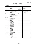
Страница 47: ...rol data 255 チェックサム Check sum 20 22 モニター発光回数 No of times for Monitor Flash 23 127 制御用データ Control data 128 130 メインコンデンサ Main condenser 131 135 制御用データ Control data 136 157 フル発光パルス Full flash pulse 158 164 マニュアル光量 Manual out put 165 166 モニター発光量 Monitor flash 167 制御用データ Control data 168 170 FP発光量 FP flash 171 172 D TTL発光量 D TTL flash 173 200 制御用データ Control data 201 207 FP発光量 FP flash EEPROM DATA SB 60...

Страница 48: ...FSA03601 R 3629 A E6 SB 600 R基板 1 R PCB 1 R基板 2 R PCB 2 ...

Страница 49: ...FSA03601 R 3629 A E7 SB 600 F基板 F PCB L基板 L PCB ...

Страница 50: ...FSA03601 R 3629 A E8 SB 600 C基板 C PCB ズーム基板 ZOOM PCB 脚基板 FOOT PCB バウンス基板 BOUNCE PCB XEーA基板 XE A PCB XEーK基板 XE K PCB ...

Страница 51: ...uminator ズームモーター Zoom motor BOUNCE 基板 BOUNCE PCB ブザー Buzzer SW 601 Zoom 位置検出 SW601 Zoom position detection キー照明用 For Key illuminator バックライト用 For Back light 書き込み用端子 Terminal for writing in スレーブ用 READY READY for Slave F 基板 L 基板 スレーブ用SPD SPD for Slave BATT 基板 外部AF補助光 External AF assist illumonator FOOT 基板 FOOT PCB Battery PCB R 基板 R PCB ...

Страница 52: ...ケース部組 R CASE UNIT Fケース部組 F CASE UNIT 電池ケース部組 Battery case WR4 WR5 WR1 ズーム基板 Zoom PCB WPスイッチ WP SWITCH WF3 P300K TCC 1 24mm 28mm 35mm 50mm 70mm 85mm DCDC DCDC Batt CR1 CR5 CR4 CR3 CR2 CRP CLR CF2 CF3 CF1 SCR IGBT XE A L501 XE K XE K2 LI LI 黄 YELLOW 茶 BROWN 白 WHITE 橙 ORANGE 赤 RED 黒 BLACK 赤 RED 黒 BLACK 赤 RED 黒 BLACK 青 BLUE 橙 ORANGE 青 BLUE 灰 GRAY 黒 BLACK 実体配線図 WIRING 黒 BLACK 灰 GRAY 紫 PURPLE 青 BLUE 緑 G...

Страница 53: ...ware IBM 3 5 inches AF 補助光用チャート Chart for AF Assist light 修理指針A 25 ページ使用 Use the page A 25 of the Repair Manual パーソナルコンピュータ Personal computer 汎用品 RJ is Not available RS232Cケーブル RS232C cable 汎用品 RJ is Not available 安定化電源 6 0V 3A Power supply 6 0V 3A 汎用品 RJ is Not available デジタルマルチメータ Digital meter 汎用品 RJ is Not available フラッシュメータ Flash meter 汎用品 RJ is Not available 工 具 TOOLS T1 ...

Страница 54: ...EBB0061 グリース G7100 Grease G7100 NET 100g TA 0002 テープ W 20mm TSE3941 シリコン TSE3941 SILICONE TSE3941 温度ヒューズ用接着剤 Glue For Thermal fuse NET 150g EDA1021 セメダインハイスーパー CEMEDINE Hi SUPER エポキシ樹脂系接着剤 Epoxy glue EDB0011 ネジロック 赤 Screw Lock RED J67017 セメダイン 575 CEMEDINE 575 その他 Others ...

Страница 55: ...3629 A 作成承認印 配布許可印 P A R T S L I S T 修 理 部 品 表 NIKON CORPORATION Tokyo Japan Recycled paper 再生紙を使用しています Printed in Japan November 2004 Copyright c 2004 by Nikon Corporation All Rights Reserved 無断転載を禁ず FSA03601 INC ...

Страница 56: ...0 2004 Distribution of Parts list CD ROM version The parts that were changed after creating the temporary parts list E mail version are shown by marks in the technical drawings and parts list Note marks are in red only for the technical drawings The creation date is inserted in the lower left hand corner of each page to help manage updating pages when printed INC ...

Страница 57: ... INC ...

Страница 58: ... INC ...

Страница 59: ...CHANGE PAGE 差替え 1 Mar 30 2007 INC ...

Страница 60: ... SEP 10 2004 INC ...

Страница 61: ... IT201 5 差替え x1 INC ...

Страница 62: ...ERY PCB UNIT 1 5 5 1C999 284 1C999 284 脚部シールド板部組 FOOT SHIELD UNIT 1 3 5 1C999 285 1C999 285 モーター部組 MOTOR UNIT 1 1 5 1C999 286 1C999 286 脚部組 FOOT UNIT 1 3 1 1C999 289 1C999 289 光ファイバー部組 OPTICAL FIBER UNIT 1 1 5 1K010 619 1K010 619 SCREW SCREW 2 1 10 1K010 620 1K010 620 SCREW SCREW 1 4 10 1K050 763 1K050 763 ワッシャー WASHER 2 4 10 1K087 520 1K087 520 原産国シール CHINA LABEL SEAL 1 4 5 1K087 587 1K087 587 ...

Страница 63: ... 307 1K103 307 ゼブラゴム RUBBER CONNECTOR 2 3 5 1K103 308 1K103 308 エンボスSWシート SWITCH SHEET 1 3 5 1K103 309 1K103 309 導光ゴム RUBBER 1 3 5 1K103 310 1 1K103 310 1 両面テープ DOUBLE SIDE ADHESIVE TAPE 1 3 5 1K103 311 1K103 311 ブザー両面テープ DOUBLE SIDE ADHESIVE TAPE 1 2 5 1K103 312 1K103 312 絶縁チューブ INSULATOR TUBE 1 5 5 1K103 314 1K103 314 リード線ガイド板 GUIDE PLATE 1 2 5 1K103 422 1K103 422 ズーム基板絶縁シート INSULA...

Страница 64: ...ートップ テスト発光 KEY TOP FLASH 1 3 5 1K220 556 1K220 556 バウンスバネ SPRING 2 4 5 1K220 560 1K220 560 ロックツマミバネ LOCK KNOB SPRING 1 3 1C999 286 5 1K220 599 1K220 599 ズームシャフトバネ ZOOM SHAFT SPRING 1 2 5 1K220 600 1K220 600 左右バウンスストップ軸バネ SHAFT SPRING 1 4 5 1K220 601 1 1K220 601 1 クリック操作板戻しバネ CLICK PLATE SPRING 1 4 5 1K220 611 1K220 611 サイドゴムA戻しバネ SIDE RUBBER SPRING 1 1 5 1K233 177 1K233 177 WP付勢バネ SP...

Страница 65: ...UBBER A 1 1 5 1K467 241 1K467 241 サイドゴムB SIDE RUBBER B 1 1 5 1K467 242 1 1K467 242 1 赤パネル RED PANEL 1 2 5 1K601 792 1K601 792 平板 PLATE 1 3 1C999 286 5 1K602 116 1K602 116 ガラスパネル GLASS PANEL 1 2 5 1K602 117 1 1K602 117 1 回転リング TURN RING 1 4 5 1K602 118 1 1K602 118 1 リングA RING A 1 4 5 1K602 119 1K602 119 リングB RING B 1 4 5 1K602 124 1K602 124 上部締結板 UPPER NUT PLATE 2 2 5 1K602 125 1K602 125 下部...

Страница 66: ... 5 1K682 866 1 1K682 866 1 ワイドパネル WIDE PANEL 1 1 5 1K682 867 1 1K682 867 1 リフレクターホルダー REFLECTOR HOLDER 1 2 5 1K682 868 1K682 868 ズームシャフトホルダー ZOOM SHAFT HOLDER 1 2 5 1K682 870 1 1K682 870 1 モーター受け台 MOTOR BASE 1 1 5 1K682 871 1 1K682 871 1 駆動部ベース板 BASE PLATE 1 1 5 1K682 872 1 1K682 872 1 クリック回転軸 CLICK ROTARY SHAFT 1 4 5 1K682 873 1K682 873 バウンス回転軸 BOUNCE ROTARY SHAFT 1 4 5 1K682 875 1 1K682 8...

Страница 67: ...01 C501 メインコンデンサ MAIN CONDENSER 1 4 C 1 F FSA03601 F F基板部組 F PCB UNIT 1 5 1 Old F 1 FSA03601 F 1 F基板部組 F PCB UNIT 1 5 1 New F801 FSA03601 F801 温度ヒューズ TEMP FUSE 1 5 5 ISO6438E FSA03601 ISO643LCD LCD 1 3 5 IT201 FSA03601 IT201 IGBT IGBT 1 5 F 5 L FSA03601 L L基板部組 L PCB UNIT 1 5 1 R FSA03601 R R基板部組 R PCB UNIT 1 3 1 Old RP07035 R 1 FSA03601 R R基板部組 R PCB UNIT 1 3 1 New RP07035 SW601 FSA03601 SW601 ...

Страница 68: ... 5 W PCON FSA03601 W PCONリード線 PCON LEAD WIRE PCON 1 5 5 WR2 FSA03601 WR2 コネクタ WR2 CONNECTOR WIRE WR2 1 3 5 WR5 FSA03601 WR5 コネクタ WR5 CONNECTOR WIRE WR5 1 2 5 W READY FSA03601 W READリード線 READY LEAD WIRE READY 1 5 5 W TRG2 FSA03601 W TRG2リード線 TRG2 LEAD WIRE TRG2 1 2 5 W VCCH FSA03601 W VCCHリード線 VCCH LEAD WIRE VCCH 1 5 5 W XEK2 FSA03601 W XEK2リード線 XE K2 LEAD WIRE XE K2 1 1 5 XE701 FSA03601 XE701...

Страница 69: ...18FD B2 14018FD SCREW SCREW 8 4 10 B2 17030FD B2 17030FD SCREW SCREW 4 2 3 10 G1 17035FD G1 17035FD SCREW SCREW 2 1 10 G1 17045FD G1 17045FD SCREW SCREW 2 1 10 H1 17030FD H1 17030FD SCREW SCREW 1 1 10 H1 17040FA H1 17040FA SCREW SCREW 22 1 3 5 10 H1 17250FD H1 17250FD SCREW SCREW 2 4 10 H1 20035FD H1 20035FD SCREW SCREW 2 1 10 H1 20055FD H1 20055FD SCREW SCREW 3 2 10 H2 20040FD H2 20040FD SCREW SC...

Отзывы: