VBA28001-R.3813.A
- A58 ・ D3100 -
[Gray]
[Orange]
[Green]
[Blue]
Solder.the.four.wires.of.the.SB.lower.cover.unit.
•
Connect.the.FPC.and.harness.
Arrange.the.wires.as.below.
User ID:INC
Страница 1: ...作成承認印 配布許可印 M サービス 計画課 REPAIR MANUAL VBA28001 Copyright 2010 by Nikon Corporation All Rights Reserved 無断転載を禁ず Printed in Japan March 2010 VBA28001 R 3813 A jmem O 52 2 3 Ebcqgel grm User ID INC ...
Страница 2: ...3 Rear button D13 LV lever D14 TFT sponge D14 SD access lamp window D14 3 Top Cover D15 SB release PCB unit D15 SB upper cover D17 SB lower cover unit D17 AF assist lamp unit D19 Top cover FPC unit D20 Command dial unit D21 Info aperture button D21 ON OFF dial D22 Mode dial unit D23 Hot shoe D24 Prism box unit D25 Screen D26 SI super impose display plate D26 LCD unit D27 G7 lens unit D27 4 Sub fra...
Страница 3: ...unit A1 Lens release button unit A2 AF sensor unit A2 Lens contact unit A3 F min SW A5 Bayonet mount A5 SQ PCB unit A7 Height adjustment of aperture lever A8 MG PCB unit A8 Shutter PCB A10 Adjustment of shutter curtain speed A14 Inspection and adjustment of flange back body back A15 Image sensor unit A16 2 Sub frame A18 Bottom plate unit A18 Radiating sheet for repair A21 Sub frame A22 SZ DC DC PC...
Страница 4: ...unit A48 4 Rear Cover A51 SD access lamp window A51 TFT sponge A51 LV lever A51 Rear button A52 LCD monitor A52 Rear FPC A53 Speaker A53 Eyepiece A55 LCD monitor cover A55 SD cover A56 5 External Appearance A57 Top cover unit A57 Adjustment of camera body except imaging A59 Firmware update A61 How to connect camera and PC A61 How to install inspection and adjustment software for camera body except...
Страница 5: ...n current value A71 Operation check of image sensor cleaning A72 Image adjustment 1 A74 Image adjustment 2 A74 Image adjustment 3 A75 Image adjustment 4 A75 Image adjustment 5 A75 Image adjustment 6 A76 Image adjustment 7 A76 Obtaining of reference value A77 Factory default setting A77 Confirmation of data A77 Version no Serial no A77 Wiring E1 Mounting Drawing E2 FUSE arrangement E3 Inspection st...
Страница 6: ...ution In disassembly re assembly be sure to use conductive mat J5033 and wrist strap J5033 5 in order to protect electric parts from static electricity Before disassembling be sure to remove batteries or AC power cord In disassembling be sure to memorize the processing state of wires and FPCs screws to be fixed and their types etc The low pass filter of the image CCD PCB is easily damaged Handle i...
Страница 7: ... 3813 A D2 D3100 B151 72 71 Remove the power connector cover 72 Remove the IF cover 71 1 External Appearance Rear cover unit Incline the battery cover unit B151 at an approx 35 as below and remove it User ID INC ...
Страница 8: ...VBA28001 R 3813 A D3 D3100 267 614 623 634 631 Remove the cover 267 Take out the screw 614 Take out the two screws 623 Take out the screw 634 Take out the two screws 631 User ID INC ...
Страница 9: ... D4 D3100 623 640 661 B26 27 Take out the two screws 640 Take out the two screws 623 Take out the screw 661 Remove the grip unit B26 Do NOT reuse the grip unit that was once removed Remove the grip cover 27 User ID INC ...
Страница 10: ...VBA28001 R 3813 A D5 D3100 411 622 410 Remove the rubber 410 and double stick tape 411 Take out the screw 622 Lift up the rear cover unit Disconnect the FPC Remove the rear cover unit User ID INC ...
Страница 11: ... 639 631 643 634 644 Front cover unit Take out the two screws 644 and one screw 639 Take out the three screws 631 Take out the one screw 643 and two screws 634 Slacken the tripod base area and remove the front cover unit User ID INC ...
Страница 12: ...646 from the front cover 24 Remove the spring 160 Remove the button 465 There are high voltage parts inside Be careful of this electric shock when you remove the cover You must discharge the main condenser according to the instruction of this repair manual after you remove the cover WARNING User ID INC ...
Страница 13: ...3813 A D8 D3100 Gray Orange Green Blue 631 632 656 Top cover unit Unsolder the four wires of the SB lower cover unit Remove the harness and FPC Take out the screws 631 632 and 656 Remove the top cover User ID INC ...
Страница 14: ...VBA28001 R 3813 A D9 D3100 B431 2 Rear Cover SD cover unit Remove the SD cover unit B431 from the rear cover unit Unhook User ID INC ...
Страница 15: ...D monitor cover 402 Peel off the double stick tape 403 Eyepiece Take out the two screws 624 and remove the eyepiece frame unit from the rear cover Remove the sponge 476 from the eyepiece frame 475 Take out the screw 621 Remove the retainer plate 266 Remove the diopter adj knob 265 User ID INC ...
Страница 16: ...100 406 621 621 621 TA 0005 10x20 x2 Red Black Peel off the two pieces of the tape TA 0005 10 20 Take out the nine screws 621 Remove the retainer plate 406 Retainer plate Unsolder the two wires of the speaker 1054 User ID INC ...
Страница 17: ...28001 R 3813 A D12 D3100 B1016 1049 1054 Rear FPC Disconnect the two FPCs While slacking the FPC see below of the LCD monitor 1049 remove the rear FPC unit B1016 Speaker Remove the speaker 1054 User ID INC ...
Страница 18: ...VBA28001 R 3813 A D13 D3100 415 1049 412 413 416 385 386 424 425 LCD monitor Remove the LCD monitor 1049 Rear button User ID INC ...
Страница 19: ...21 408 LV lever Take out the two screws 619 Remove the retainer plate 471 spring 472 and LV lever 470 TFT sponge Remove the two sponges 404 and two sponges 405 SD access lamp window Remove the adhesive EDC0021 then remove the SD access lamp window 408 User ID INC ...
Страница 20: ...5 D3100 618 36 C 8008B 1053 Black White 3 Top Cover SB release PCB unit Remove the Super X C 8008B then remove the microphone 1053 Unsolder the two wires Take out the screw 618 and remove the driving magnet 36 User ID INC ...
Страница 21: ... the three screws 617 Unhook the top cover FPC unit B1007 in the numeric order from to and then remove the SB release PCB 455 Remove the SB release lever 456 Remove the SB lock lever 309 and spring 458 together Remove the spring 458 from the SB lock lever 309 User ID INC ...
Страница 22: ...e Gray Orange 305 Blue SB lower cover unit Unhook the spring 305 Unhook the spring 459 and spring 305 Unsolder the two wires Release the four wires from the four guides SB upper cover Take out the two screws 628 Remove the SB upper cover 301 Guide User ID INC ...
Страница 23: ...VBA28001 R 3813 A D18 D3100 308 B302 Release hooks Remove the roller 308 while releasing the hooks Remove the SB lower cover unit B302 Pull out the wires User ID INC ...
Страница 24: ...325 629 Black Black Red 1027 AF assist lamp unit Unsolder the two wires of the harness 1027 Uncoated Unsolder the two wires of the AF assist lamp unit B325 Take out the screw 629 and remove the AF assist lamp unit B325 User ID INC ...
Страница 25: ...t Remove the five solders of the hot shoe Take out the three screws 617 Solder 5 Remove the top cover FPC unit B1007 Caution When the top cover FPC unit is removed be careful that the inner click spring 361 and click ball 362 in the command dial may pop out User ID INC ...
Страница 26: ...VBA28001 R 3813 A D21 D3100 B360 361 362 381 Command dial unit Remove the command dial unit B360 Remove the click ball 362 and click spring 361 Info aperture button Remove the button 381 User ID INC ...
Страница 27: ...VBA28001 R 3813 A D22 D3100 615 348 347 B345 ON OFF dial Take out the two screws 615 Remove the ON OFF SW brush 348 and ON OFF click plate 347 Remove the power dial unit B345 User ID INC ...
Страница 28: ...62 374 Mode dial unit Take out the screw 616 Remove the contact brush 372 and click spring 373 Remove the mode dial unit B371 Unhook Take out the two screws 663 Remove the contact brush 375 click ball 362 and release mode dial 374 362 close up User ID INC ...
Страница 29: ...VBA28001 R 3813 A D24 D3100 B317 316 318 322 627 Hot shoe Take out the four screws 627 Remove the holder plate 322 hot shoe spring 318 hot shoe 316 and hot shoe mold unit B317 User ID INC ...
Страница 30: ...m box unit Note The prism box unit can be disassembled until the stage shown from page D26 to D28 Further disassembly can not be made ref parts list Disconnect the two FPCs Take out the two screws 613 Remove the prism box unit User ID INC ...
Страница 31: ...super impose display plate Remove the rubber 281 Remove the SI display plate 13A Remove the rubber 285 Caution The SI display plate 13 tends to be scratched easily so do NOT wipe it out with alcohol If dust or dirt is attached blow it with a blower Screen User ID INC ...
Страница 32: ...26 4 5 4 5 LCD unit Take out the two screws 650 Remove the LCD unit B1045 and tape 291 G7 lens unit Disconnect the FPC s one end of the AE CCD and remove the other end from the shading plate 271 Peel off the double stick tape TA 0026 4 5 4 5 User ID INC ...
Страница 33: ...264 268 Remove the shading plate 271 and sponge 293 Unhook Pull out the pin 262 Remove the G7 lens unit Release from the groove side Be careful of pop out of the spring Pushing from the prism side will make it easier to pull out 262 User ID INC ...
Страница 34: ... 13x28 Main condenser Peel off the tape TA 0015 13 28 Unsolder the two wires from the main condenser 1043 Remove the main condenser 1043 Peel off the double stick tape 141 4 Sub frame tentative IF holder Take out the screw 633 Remove the IF holder 70 User ID INC ...
Страница 35: ... PCB unit Peel off the tape TA 0015 13 18 Remove the three FPCs and harness Take out the four screws 656 and one screw 607 Remove the TOGO PCB unit B2001 Disconnect the connection FPC 1015 from the connectors in the numeric order from to Remove by sliding inwards User ID INC ...
Страница 36: ...rple x2 Black Red Battery box unit Remove the spring 158 Take out the one screw 638 and two screws 643 Disconnect the FPC by slightly tilting the battery box sideways Unsolder the four wires of the power drive PCB Remove the harness User ID INC ...
Страница 37: ...e 1026 Black Red 658 664 1004 Unsolder the two wires of the harness 1026 Unsolder the two wires of the condenser The battery box unit will come off Take out the two screws 658 and one screw 664 Remove the power drive PCB 1004 User ID INC ...
Страница 38: ...VBA28001 R 3813 A D33 D3100 147 651 145 150 Remove the O ring 147 Take out the two screws 651 and remove the eyelet 145 Peel off the sheet 150 User ID INC ...
Страница 39: ...VBA28001 R 3813 A D34 D3100 159 154 155 EDC0021 156 Remove the GND plate 159 Peel off the sheet 154 Remove the adhesive EDC0021 and remove the pin 155 from the battery box 156 User ID INC ...
Страница 40: ...3100 480 481 607 Shield plate unit Take out the three screws 607 Displace slightly the GND plate of the image sensor unit and remove the shield plate unit Peel off the tape 481 from the shield plate 480 GND plate User ID INC ...
Страница 41: ...two screws 656 Remove the sub frame unit When this is removed be careful not to get caught by a wire of the condenser Disconnect the connection FPC 1020 SZ DC DC PCB unit Take out the two screws 656 Remove the SZ DC DC PCB unit B1002 Remove the four wires Be careful not to get caught by a wire of the condenser User ID INC ...
Страница 42: ... D37 D3100 147 657 145 62 63 63 TA 0016 5 8 Sub frame Remove the O ring 147 Take out the two screws 657 and remove the eyelet 145 Remove the two rubbers 63 from the sub frame 62 Peel off the tape TA 0016 5 8 User ID INC ...
Страница 43: ...te unit Peel off the shield sheet 65 from the front body unit Heat radiating sheet Peel off the heat radiating sheet of the image sensor unit B3051 from the bottom plate unit Take out the two screws 647 and remove the bottom plate unit User ID INC ...
Страница 44: ...VBA28001 R 3813 A D39 D3100 TA 0026 5 40 Black Red Remove the two wires of the condenser Peel off the tape TA 0026 5 40 User ID INC ...
Страница 45: ...813 A D40 D3100 630 68 61 65 Take out the four screws 630 and remove the tripod base 68 from the bottom plate 61 Attach by fitting in each round hole Attach the shield sheet 65 to the bottom plate unit User ID INC ...
Страница 46: ... D3100 B3051 634 3 87 107 3 80 3 59 Image sensor unit Peel off the tape 59 Take out the three screws 634 and remove the three washers 80 Remove the image sensor unit B3051 Remove the washers 87 107 5 Front Body User ID INC ...
Страница 47: ... SQ PCB unit in the direction of the arrow to raise the mirror Then set the lever s position of the MG PCB unit to the OK position as below Caution It may require turning the gear several times to become at OK position Peel off the tape TA 0016 5 8 from the lens contact unit B2113 Unsolder the three wires of the harness 1028 User ID INC ...
Страница 48: ...13 A D43 D3100 612 2004 612 196 604 2003 Take out the two screws 612 Remove the brake plate 196 Take out the screw 604 Remove the retainer plate 2003 Take out the screw 612 Remove the retainer plate 2004 User ID INC ...
Страница 49: ...2 178 179 Take out the screw 608 Remove the holder plate 2002 Caution Be careful that the spring may pop out To avoid deformation of 2002 do NOT hold the other areas than indicated in red Unhook the springs 178 and 179 Unhook User ID INC ...
Страница 50: ...VBA28001 R 3813 A D45 D3100 B2016 178 2015 Remove the retainer plate 2015 Remove the shutter curtain unit B2016 and also remove the spring 178 User ID INC ...
Страница 51: ... 619 2001RP Remove the shutter curtain unit B2016 and also remove the spring 179 Take out the screw 619 Remove the shutter PCB unit 2001RP Caution To avoid deformation of 2001RP do NOT hold the other areas than indicated in red User ID INC ...
Страница 52: ...VBA28001 R 3813 A D47 D3100 607 B176 Black Red MG PCB unit Unsolder the four wires Take out the two screws 607 Remove the MG PCB unit B176 User ID INC ...
Страница 53: ...B unit Turn the gear indicated in red clockwise to lower the mirror Loosen the four screws 602 By slightly lifting the SQ PCB unit remove the spring of the SQ unit from the hook of the mirror unit Loosen the four screws 602 Spring User ID INC ...
Страница 54: ...ure lever section of the SQ PCB unit B2177 from the front body by releasing from a gap see below Peel off the shading sheet 29 Bayonet mount Take out the five screws 653 and one screw 654 Remove the bayonet mount 111 Remove the three bayonet mount springs 112 User ID INC ...
Страница 55: ...VBA28001 R 3813 A D50 D3100 655 137 131 489 Take out the screw 655 Remove the GND plate 137 and also remove the F min coupling block 131 Remove the gasket 489 Boss User ID INC ...
Страница 56: ... Remove the solder bridge that joints the F min SW 133 and the FPC of the lens contact unit B2113 Take out the screw 668 and remove the F min SW 133 Lens contact unit Remove the solder bridge Take out the two screws 650 and remove the GND plate 138 Remove solder bridge Remove solder bridge User ID INC ...
Страница 57: ...52 D3100 652 121 B2113 TA 0026 6 11 Take out the screw 652 Remove the lens release SW 121 Peel off the FPC of the lens contact unit B2113 by flicking it up Remove the double stick tape TA 0026 6 11 Boss Guide User ID INC ...
Страница 58: ... B116 119 115 648 x 2 AF sensor unit Take out the three screws 162 with the hexagonal key φ1 5mm Remove the AF sensor unit B2163 Peel off the tape 39 from the AF sensor unit B2163 Remove the three springs 161 Lens release button unit User ID INC ...
Страница 59: ...0 662 Mirror unit Remove the super X C 8008B from the main mirror shafts 198 and 199 Remove the main mirror shafts 198 and 199 Remove the mirror unit B2231 Peel off the shading sheet 238 and 239 and sheet 496 Take out the two screws 662 and remove the holder 30 User ID INC ...
Страница 60: ...ly 1 Front Body Mirror unit Mount the holder 30 and tighten the two screws 662 Attach the sheet 496 shading sheets 238 and 239 Mount the mirror unit B2231 and attach the main mirror shafts 198 and 199 Apply the adhesive C 8008B to the main mirror shaft Attaching position User ID INC ...
Страница 61: ...nit Attaching position AF sensor unit Attach the three springs 161 Attach the tape 39 to the AF sensor unit B2163 Mount the AF sensor unit B2163 Turn the three screws 162 all the way with the hexagonal key φ1 5mm but not too tightly and then give each screw two turns counterclockwise User ID INC ...
Страница 62: ...VBA28001 R 3813 A A3 D3100 B2113 Lens contact unit While lifting the FPC mount the lens contact unit B2113 Mountain fold Valley fold Mountain fold User ID INC ...
Страница 63: ...8 TA 0026 6 11 Boss Guide Attach the double stick tape TA 0026 6 11 Mount the lens release SW 121 Tighten the screw 652 Mount the GND plate 138 and tighten the two screws 650 Make solder bridge Make solder bridge Within this range User ID INC ...
Страница 64: ...TA 0009 5 7 F min SW Mount the F min SW 133 and tighten the screw 668 Make a solder on the F min SW 133 and the FPC of the lens contact unit B2113 Attach the tape TA 0009 5 7 Bayonet mount Attach the gasket 489 Within this range Solder User ID INC ...
Страница 65: ...e F min coupling block 131 and mount the GND plate 137 in the numeric order from to by fitting the boss Tighten the screw 655 Boss Attach the three bayonet springs 112 Mount the bayonet mount 111 Tighten the five screws 653 and one screw 654 in the numeric order from to User ID INC ...
Страница 66: ...Mount the SQ PCB unit B2177 by fitting its aperture lever section in a gap of the front body Attaching position Tighten the four screws 602 temporarily With the slightly lifting the SQ unit hook the spring to the mirror unit Do final tightening of the four screws 602 in the numeric order from to After assembling the above check whether the aperture lever section works smoothly Direction for positi...
Страница 67: ...f the MG PCB unit to the OK position as below Caution It may require turning the gear several times to become at OK position Height adjustment of aperture lever Refer to Height adjustment of aperture lever of ADJUSTMENT Separate Volume for details Standard 3 3 3 6 mm Tool device J18004 Aperture lever positioning gauge SQ PCB unit lever s NG Not Good NG Not Good User ID INC ...
Страница 68: ...13 A A9 D3100 607 B176 Black Red Solder the four wires Mount the MG PCB unit B176 Tighten the two screws 607 in the numeric order from to After the above tightening check whether the lever works smoothly User ID INC ...
Страница 69: ...ount the shutter PCB unit 2001RP Caution To avoid deformation of 2001RP do neither hold the other areas than indicated in red nor let 2001RP be placed on the shaft Tighten the screw 619 Direction for positioning 2001RP must not be placed on the shaft User ID INC ...
Страница 70: ...8 B2016 Mount the shutter curtain unit B2016 Attach the spring 179 At this point do NOT engage the hook Mount the retainer plate 2015 This circle must face the penta prism side Attach the spring 178 Mount the shutter curtain unit B2016 User ID INC ...
Страница 71: ...2 178 179 Hook the springs 178 and 179 each Mount the holder plate 2002 Caution Be careful that the spring may pop out To avoid deformation of 2002 do NOT hold the other areas than indicated in red Tighten the screw 608 Hook User ID INC ...
Страница 72: ...4 2003 612 196 612 2004 Mount the brake plate 196 and tighten the two screws 612 Mount the retainer plate 2003 Tighten the screw 604 Boss Direction for positioning Mount the retainer plate 2004 and tighten the screw 612 User ID INC ...
Страница 73: ...BODY Select Yes Turn the camera OFF and disconnect the camera from PC Remove the rear cover Remove the FPC of the SQ unit Refer to Adjustment of shutter curtain speed of ADJUSTMENT Separate Volume for details Setting 1 4000 sec Standard Front curtain Rear curtain 3 45 3 55 ms Difference in speed between front and rear curtain fm 0 02 to 0 02 ms Caution When the shutter PCB and MG PCB are replaced ...
Страница 74: ...10V 5A Power connector EP 5A AC adapter EH 5 or EH 5A Curtain speed adj dummy body Tool Device J19004 1 J18001 1 J11388 Dial indicator and stand Body back focus gauge Flat type measuring terminal 87 1K106 553 washer T 0 05 88 1K106 554 washer T 0 06 89 1K106 555 washer T 0 07 90 1K106 556 washer T 0 08 91 1K106 557 washer T 0 09 92 1K106 558 washer T 0 10 93 1K106 559 washer T 0 11 94 1K106 560 wa...
Страница 75: ...mage sensor unit Mount the image sensor unit B3051 Put the three washers 80 Tighten the three screws 634 in the numeric order from to Attach the tape 59 Place the tape under the tip of the screw Attaching position Direction for positioning User ID INC ...
Страница 76: ...A17 D3100 1028 Black Red Gray TA 0016 5 8 Solder the three wires of the harness 1028 Attach the tape TA 0016 5 8 Arrange the wires Fit the tape based on the below central line and the corner Arrange the wires User ID INC ...
Страница 77: ...100 630 68 65 61 2 Sub frame Bottom plate unit Attach the tripod base 68 to the bottom plate 61 and tighten the four screws 630 Attach by fitting each round hole Attach the shield sheet 65 to the bottom plate unit User ID INC ...
Страница 78: ... D3100 TA 0026 5 40 Black 4 0cm Red 4 5cm Black 6 7cm Red 6 2cm Attach the double stick tape TA 0026 5 40 to the bottom plate 61 and attach the two wires of the condenser on the tape Attaching position Dent here User ID INC ...
Страница 79: ... the bottom plate unit on the front body and tighten the two screws 647 in the numeric order from to Attach the heat radiating sheet of the image sensor unit B3051 to the bottom plate unit Attach the shield sheet 65 to the front body unit as below User ID INC ...
Страница 80: ...peeled off attach the radiating sheet for repair 57 as below Attach 57 beneath the remaining sheet by fitting in the concave portions Cut off the heat radiating sheet by 5mm Attach a new 57 by fitting in concave portions Peel off 57 of the 1st time 1st time 2nd time and later User ID INC ...
Страница 81: ... D3100 147 657 145 62 63 63 TA 0016 5 8 Sub frame Attach the two rubbers 63 to the sub frame 62 Attach the tape TA 0016 5 8 Mount the eyelet 145 and tighten the two screws 657 Mount the O ring 147 Fold backwards User ID INC ...
Страница 82: ...VBA28001 R 3813 A A23 D3100 656 B1002 purple x2 Black Red 62 SZ DC DC PCB unit Solder the four wires Mount the SZ DC DC PCB unit B1002 on the sub frame 62 Tighten the two screws 656 User ID INC ...
Страница 83: ... body unit Tighten the two screws 635 with the torque driver set value 12N cm in the numeric order from to Tighten the two screws 656 in the numeric order from to and connect the FPC 1020 to the image sensor unit B3051 Attach the tape 481 to the shield plate 480 Attaching position GND plate Be careful NOT to pinch any of the condenser wires FPCs or GND plate User ID INC ...
Страница 84: ...813 A A25 D3100 607 Mount the shield plate unit so that the GND plate of the image sensor unit is not pinched Tighten the three screws 607 GND plate Pinch in as below Fit the image sensor unit as below User ID INC ...
Страница 85: ...1 R 3813 A A26 D3100 155 EDC0021 156 159 154 Battery box unit Put the pin 155 into the battery box 156 and apply the adhesive EDC0021 Attach the sheet 154 Attaching position Mount the GND plate 159 User ID INC ...
Страница 86: ...VBA28001 R 3813 A A27 D3100 150 147 651 145 Mount the eyelet 145 and tighten the two screws 651 Mount the O ring 147 Attach the sheet 150 Attaching position User ID INC ...
Страница 87: ... A A28 D3100 658 664 1004 Black Red Red Blue 1026 Mount the power drive PCB 1004 Tighten the two screws 658 and one screw 664 Solder the two wires of the condenser Solder the two wires of the harness 1026 User ID INC ...
Страница 88: ...ody and battery box mount the battery box unit Tighten the two screws 643 and one screw 638 Connect the harness with the battery box being tilted Solder the four wires of the power drive PCB Connect the FPC Attach the spring 158 Arrange the harnesses so that they are not pinched in the sub frame User ID INC ...
Страница 89: ...the TOGO PCB unit B2001 Tighten the four screws 656 and one screw 607 Connect the three FPCs Attach the tape TA 0015 13 18 Put by sliding outwards SD insertion section Be careful NOT to pinch the harnesses in the SD insertion section Do NOT pinch the shield plate inside the sub frame The pattern surface must face downwards Attaching position User ID INC ...
Страница 90: ...271 293 NKS 401H OK NG G7 lens unit Mount the G7 lens unit Insert the pin 262 Put into the groove Mount the shading plate 271 and sponge 293 Mounting position Be careful that the spring may pop out Dipping Inserting position of pin User ID INC ...
Страница 91: ...32 D3100 TA 0026 4 5 4 5 271 Hook Attach the double stick tape TA 0026 4 5 4 5 Attach the FPC of the AE CCD to the shading plate 271 Put inside the guide Connect the FPC Put inside the guide Attaching position User ID INC ...
Страница 92: ...VBA28001 R 3813 A A33 D3100 650 B1045 291 LCD unit Mount the LCD unit B1045 Tighten the two screws 650 Attach the tape 291 Attaching position of 291 User ID INC ...
Страница 93: ...Attach the rubbers 281 and 285 Caution The SI display plate 13A tends to be scratched easily so do NOT wipe it out with alcohol If dust or dirt is attached blow it with a blower Attaching position Screen Surface with irregularities must face the prism side while surface without irregularities must face front body User ID INC ...
Страница 94: ...Angle adjustment of main mirror and sub mirror Refer to Angle adjustment of main mirror and sub mirror and How to do positioning of sub mirror for 51 angle of ADJUSTMENT Separate Volume for details Standard angle of sub mirror 51 Main Sub 51 Up down deviation 0 4 0 3 Left right deviation 0 10 Tool Device J19132 J19132D J15442 Main Sub mirror angle inspection tool 54 measurement use mirror Reflecti...
Страница 95: ...nge fm 0 06 to 0 06mm 0 06 or smaller Increase the washers to increase thickness 0 06 or larger Decrease the washers to reduce thickness IF holder Mount the IF holder 70 and tighten the screw 633 Tool Device J19001 J18010 J15441 focus collimator F 600mm Infinity standard lens 50 1 8 Infinity focus adjustment screen 297A 1K603 712 washer T 0 10 297B 1K603 713 washer T 0 20 User ID INC ...
Страница 96: ...n condenser unit based on the mounting position of the front body so that the end of the attached double stick comes to the mounting position line Solder the two wires on the main condenser unit Attach the tape TA 0015 TA 0015 13 28 Attach the double stick tape based on the polar mark of the condenser Mounting position Direction for positioning User ID INC ...
Страница 97: ...over and then set time zone and date and time on the menu Mount the front cover 24 and tighten the three screws 631 for temporary assembly Mount the battery cover unit B151 Refer to Inspection and adjustment for AE CCD positioning of ADJUSTMENT Separate Volume for details Inspection for AE CCD positioning Tool Device J15428 J63070 J18267 J15443 J15444 Use Nikon products AE CCD use chart board Colo...
Страница 98: ...s 631 and remove the front cover 24 Discharge the main condenser There are high voltage parts inside Be careful of this electric shock when you remove the cover You must discharge the main condenser according to the instruction of this repair manual after you remove the cover WARNING User ID INC ...
Страница 99: ...17 316 318 322 627 NKS 401H LEN317A 3 Top Cover Hot shoe Attach the holder plate 322 hot shoe spring 318 hot shoe 316 and hot shoe mold unit B317 Tighten the four screws 654 Mode dial unit Mount the release mode dial 374 User ID INC ...
Страница 100: ... 362 B371 616 372 373 LEN317A Attach the click ball 362 and contact brush 375 Tighten the two screws 663 Mount the mode dial unit B371 Attach the contact brush 372 and click spring 373 Tighten the screw 616 Hook 362 close up User ID INC ...
Страница 101: ... 348 347 B345 381 LEN317A ON OFF dial Attach the power dial unit B345 at ON position and then attach the ON OFF click plate 347 and ON OFF SW brush 348 Tighten the two screws 615 Info aperture button Attach the button 381 User ID INC ...
Страница 102: ...0 B360 361 362 LEN317A LEN317A Command dial unit Mount the command dial unit B360 Dipping Put the click ball 362 all the way seated Put the click spring 361 by inserting side first and then push side inside as below User ID INC ...
Страница 103: ...VBA28001 R 3813 A A44 D3100 CFD 490Z B1007 617 Top cover FPC unit Mount the top cover FPC unit B1007 Boss Make solder 5 Tighten the three screws 617 Make five solders on the hot shoe User ID INC ...
Страница 104: ...lamp unit Mount the AF assist lamp unit B325 by fitting the boss position and tighten the screw 629 Solder the two wires Solder the two wires of the harness 1027 Boss Uncoated Guide SB lower cover unit Mount the SB lower cover unit B302 while extending it as indicated by the arrow User ID INC ...
Страница 105: ...A A46 D3100 308 CFD 409Z Blue Red Green Blue Gray Orange Attach the roller 308 and hook it Put the wires through the hole Arrange the four wires along the four guides Solder the two wires Hook Dipping Guide User ID INC ...
Страница 106: ... A A47 D3100 305 459 301 628 305 SB upper cover Mount the SB upper cover 301 Tighten the two screws 628 Attach the spring 305 by fitting in the groove Attach the spring 459 Hook the spring 305 Hook Groove User ID INC ...
Страница 107: ...5 309 SB release PCB unit Attach the spring 458 to the SB lock lever 309 Attach the spring and SB lock lever together on the top cover Mount the SB release lever 456 456 must be engaged with the SB lock lever 309 The spring 305 must fit in the groove User ID INC ...
Страница 108: ...net 36 and tighten the screw 618 Solder the two wires While hooking the top cover lever FPC unit B1007 in the numeric order from to mount the SB release PCB 455 Tighten the three screws 617 The tip of 458 must come out from the below indicated in red of the SB release PCB 455 User ID INC ...
Страница 109: ...VBA28001 R 3813 A A50 D3100 1053 C 8008B Attach the microphone 1053 and apply the adhesive C 8008B User ID INC ...
Страница 110: ... lamp window Attach the SD access lamp window 408 and apply the adhesive EDC0021 TFT sponge By fitting in the groove of the rear cover attach the two sponges 404 and two sponges 405 LV lever Attach the LV lever 470 spring 472 and retainer plate 471 Then tighten the two screws 619 Dipping User ID INC ...
Страница 111: ...VBA28001 R 3813 A A52 D3100 415 412 413 416 385 386 424 425 1049 LCD monitor Mount the LCD monitor 1049 Rear button User ID INC ...
Страница 112: ...001 R 3813 A A53 D3100 B1016 1049 1054 Speaker Attach the speaker 1054 Rear FPC Pass the FPC of the LCD monitor 1049 through the hole of the rear FPC unit B1016 for assembly Connect the two FPCs User ID INC ...
Страница 113: ...VBA28001 R 3813 A A54 D3100 406 621 621 621 TA 0005 10x20 x2 Mount the retainer plate 406 Tighten the nine screws 621 Attach the two pieces of the tape TA 0005 10 20 Attaching position User ID INC ...
Страница 114: ...retainer plate 266 Tighten the screw 621 Attach the sponge 476 to the eyepiece frame 475 Mount the eyepiece frame unit on the rear cover and tighten the two screws 624 Solder the two wires of the speaker 1054 LCD monitor cover Attach the double stick tape 403 Mount the LCD monitor cover 402 Attaching position User ID INC ...
Страница 115: ...over Attach the SD cover unit B431 to the rear cover unit Hook Caution When the SD cover is closed the shaft may be caught by the click plate sometimes In this case push the shaft in the direction of the arrow Shaft Click plate User ID INC ...
Страница 116: ...VBA28001 R 3813 A A57 D3100 631 632 656 5 External Appearance Top cover unit Lay the wires and FPC aside as below and mount the top cover unit Tighten the screws 631 632 and 656 User ID INC ...
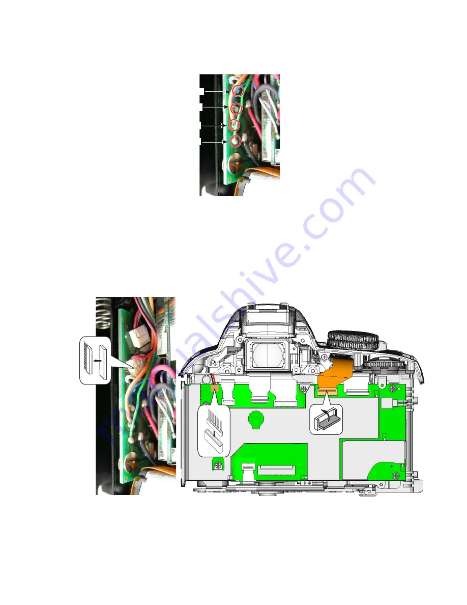
Страница 117: ...VBA28001 R 3813 A A58 D3100 Gray Orange Green Blue Solder the four wires of the SB lower cover unit Connect the FPC and harness Arrange the wires as below User ID INC ...
Страница 118: ... diopter adjustment knob all the way to the right and mount the rear cover unit Tighten the screws 631 and 623 for temporary assembly Insert a paper etc into the battery box in order to secure the power connector EP 5A Then confirm that the power can be ON Be careful NOT to touch the discharging areas and condenser Diopter adj knob User ID INC ...
Страница 119: ...uracy Shutter curtain unit TOGO PCB unit Power drive PCB AF sensor unit Top cover unit or SB lower case unit SZ DC DC PCB unit Prism box unit SQ PCB unit MG PCB unit Front body unit Adj Insp only When the TOGO PCB unit has been replaced be sure to update the Firmware of MAIN RISC and the compensation data on lens distortion before writing the initial values However the initial values for imaging w...
Страница 120: ...etails Tool Device J65153 Camera body adjustment software Inspection and adjustment for AE accuracy Refer to Inspection and adjustment for AE accuracy of ADJUSTMENT Separate Volume for details Tool Device J19123 RJ is unavailable J18267 J18498 J18499 Use Nikon product EF 1 EF 8000 LENS AF50 1 4D Lens AF 28 2 8D Lens AF S VR 70 300 4 5 5 6 Lens AF 70 300 4 5 6D Shutter tester 70 300mm lens J18360 P...
Страница 121: ...is disused For substitutes refer to TIE 03045 J15407 J15409 J63070 J63068 J11374 Multi cam 2000 AF chart Chart board Color viewer Luminance meter BM 3000 Jack 200 200 mm J19123 RJ is unavailable J18230 Use Nikon product EF 1 EF 8000 YAW PITCH adjustment tool Hexagonal key φ 1 5mm Power connector EP 5A Shutter tester J19124 J18393 J15443 J15444 Standard lens or sub standard lens AF 50 1 4D Z light ...
Страница 122: ... details Rewriting of offset value of AF adj lens Refer to Rewriting of offset value of AF adj lens of ADJUSTMENT Separate Volume for details Confirmation of data Refer to Confirmation of data of ADJUSTMENT Separate Volume for details Switch information monitor Refer to Switch information monitor of ADJUSTMENT Separate Volume for details Inspection of sequence operation Refer to Inspection of sequ...
Страница 123: ...Lift the rear cover unit and disconnect the FPC Remove the rear cover unit There are high voltage parts inside Be careful of this electric shock when you remove the cover You must discharge the main condenser according to the instruction of this repair manual after you remove the cover WARNING User ID INC ...
Страница 124: ...3 A A65 D3100 646 160 465 24 Front cover unit Attach the spring 160 to the front cover 24 Tighten the two screws 646 Attach the button 465 Mount the front cover unit while lifting the tripod base section User ID INC ...
Страница 125: ...VBA28001 R 3813 A A66 D3100 643 634 644 639 631 644 Tighten the two screws 634 and one screw 643 Tighten the three screws 631 Tighten the two screws 644 and one screw 639 User ID INC ...
Страница 126: ...00 411 622 410 Rear cover unit Connect the FPC Turn the diopter adj knob all the way to the right and mount the rear cover unit Tighten the screw 622 Attach the double stick tape 411 and rubber 410 Diopter adj knob User ID INC ...
Страница 127: ...VBA28001 R 3813 A A68 D3100 631 267 614 623 634 Tighten the two screws 631 Tighten the screw 634 Tighten the two screws 623 Tighten the screw 614 Attach the cover 267 User ID INC ...
Страница 128: ... A A69 D3100 661 B26 27 623 640 Mount the grip unit B26 Do NOT reuse the grip unit that was once removed Attach the grip cover 27 Tighten the screw 661 Tighten the two screws 640 Tighten the two screws 623 User ID INC ...
Страница 129: ...VBA28001 R 3813 A A70 D3100 71 B151 72 MZ 800SEL Mount the battery cover unit B151 Attach the power connector cover 72 Mount the IF cover 71 User ID INC ...
Страница 130: ... Main SW OFF NOT any button pressed 200μA or less Main SW ON Half release timer OFF 190μA or less Main SW ON Half release timer ON 250mA or less Main SW ON TFT monitor Light up 280mA or less During LV Live View 550mA or less During recording movies 700mA or less Tool Device Use Nikon product Power supply 10V 5A Digital meter Converted power connector EP 5A User ID INC ...
Страница 131: ...age sensor cleaning Refer to Operation check of image sensor cleaning of ADJUSTMENT Separate Volume for details Setting of oscilloscope In case of YOKOGAWA made DL1540 INPUT DC TRIGGER MODE AUTO TRIGGER LEVEL 4 0V TRIGGER SOURCE CH1 TRIGGER TYPE EDGE CH POSITION 4 00div CH COUPLING DC PROBE 1 1 FILTER Bandwidth FULL FILTER Smooth ON TIME DIV 500ms div V DIV 500mv div CH1 OFFSET Adjust so that the ...
Страница 132: ... Shutter AF sensor unit SZ DC DC PCB unit Prism box unit TOGO PCB unit Power drive PCB Image sensor unit LCD monitor unit License sheet SQ PCB unit MG PCB unit Front body unit In other cases than replacements of the parts if users point out the problems perform the image sensor cleaning operations inspections Necessary inspection and adjustment of imaging when parts are replaced Necessary Inspecti...
Страница 133: ...3070 J63085 J63086 J63087 Imaging adj tool lens Color viewer Filter SP1 Filter SP2 Filter SP3 J63068 LUMINANCE METER BM 3000 Image adjustment 1 Adjustment item Offset adjustment Refer to Offset adjustment of Imaging adjustment of ADJUSTMENT Separate Volume for details G Level output target value 130 LSB Standard 125 135 LSB Tool Device J61185 J63070 J63085 J63086 J63087 Imaging adj tool lens Color...
Страница 134: ...t Shading adjustment Refer to Sensitivity adjustment Sensitivity ratio adjustment Shading adjustment of Imaging adjustment of ADJUSTMENT Separate Volume for details Tool Device J63070 J18191 J61185 J63068 Color viewer ND filter 8 Imaging adj tool lens LUMINANCE METER BM 3000 Image adjustment 5 Adjustment item Color adjustment Refer to Color adjustment of Imaging adjustment of ADJUSTMENT Separate V...
Страница 135: ...ustment of shutter via shot image Inspection of saturation value Refer to Inspection and adjustment of shutter via shot image Inspection of saturation value of Imaging adjustment of ADJUSTMENT Separate Volume for details Tool Device J63070 J18191 J61185 J63068 Color viewer ND filter 8 Imaging adj tool lens LUMINANCE METER BM 3000 Tool Device J19123 RJ is unavailable J61185 J63068 EF 1 EF 8000 Imag...
Страница 136: ...nce value to be obtained for Sensitivity and Sensitivity ratio Sensitivity ratio color adjustment Refer to Obtaining of reference value of ADJUSTMENT Separate Volume for details Tool Device J61241 J61244 J63112 J63113 Tool body Imaging reference body D3100 color adj body Color adjusting device SG chart J18498 J63066 J63114 J11374 J63068 Lens AF 28 2 8D D1 Filter holder Filter LB120 Jack 200 200 mm...
Страница 137: ...er Aperture Mg Pop up Mg SB flashing unit TFT monitor Pressure bonding Soldering bridge Soldering bridge Soldering bridge Soldering bridge Soldering bridge Soldering bridge Connector connection Connector connection Connector connection Connector connection Connector connection Connector connection Connector connection Connector connection Connector connection Connector connection Connector connect...
Страница 138: ...in 1017 33pin 15pin CN600 1053 27pin SQ Mg 1Mg 2Mg APPI PowerDrv 1004 5pin 33pin 10pin SQ SW 15pin Popup 31pin 75pin AV SW Fmin SW 31pin SW SZ SZDCDC FPC 1020 4pin MIC 17pin SILED 1041 Mounting Drawing TOGO PCB UNIT IMAGE SENSOR UNIT AF SENSOR UNIT SZ DC DC PCB BAYONET MOUNT SQ BASE UNIT TOP COVER FPC UNIT PN LCD UNIT REAR DISPLAY FPC UNIT LENS CONTACT UNIT HOT SHOE POPUP MG SPD AF ASSIST LAMP UNI...
Страница 139: ...00 2QYGT 48 ၮ 2QYGT 48 2 5WTH HCEG ࡅࡘ 75 5 75 ߇ಾࠇߚߣ߈ߩ ࠞࡔ 㔚Ḯ ࠄߕ ޕ 2QYGT 48 ၮ ⵣ 2QYGT 48 2 4GXGTUG HCEG 1S460 012 FUSE arrangement Phenomenon when FUSE has blown out The power is not turned on PowerDRV PCB Surf face User ID INC ...
Страница 140: ...ss gauge Size Force Shutter release button Aperture lever Main mirror Sub mirror Infinity focus Protrusion 1 23 0 2 mm Halfway pressing force 0 98 0 49 N 100 50gf Halfway pressing stroke 0 5 0 2 mm Releasing force 2 55 0 69 N 260 70gf Releasing stroke 0 7 0 25 mm Full pressing stroke 0 25 0 1 mm from pressing halfway Difference btwn half pressing and releasing force 0 5N or more 51 gf gram force o...
Страница 141: ...ed accuracy Variation Shutter curtain speed Shutter curtain bound Synchronization Speed at more than 1 2000 0 55 EV 1 2000 sec 0 35EV From 1 2000 to 30 sec 0 25EV From 1 4000 to 1 2000 sec 0 4EV or less From 1 2000 to 1 1000 sec 0 3EV or less From 1 1000 to 30 sec 0 25 EV or less Both front and rear curtains up down 16 4 mm or less approx 3 7 ms Black white bound within frame None Time lag Fm 0 05...
Страница 142: ...inder field frame and measure the angle tilt AF50 1 8D F5 6 align the bottom line of the finder s FOV with the chart line and shoot pic measure a tilt of the chart line of the pic AF50 1 8D F5 6 check the actual pic with 3m distance from object of shooting Vernier caliper Eye point tool Visual check Idle consumption current Operating time consumption current accumulated Main SW OFF Do NOT press an...
Страница 143: ...ng mode Continuous VR OFF luminance face LV12 image quality BASIC image size M white balance A Lens AF S VR 18 55 3 5 5 6G Temperature 20 0 Operation Repeat the following cycle Press halfway Format card Repeat the below framed instruction When the number of shots remaining becomes 0 insert remove card Format card Caution Assuming that the power SW becomes off every 10 frame release perform ISC ope...
Страница 144: ...ive view Wait 15 mins Stop LV Wait 15 mins Time taking LV and accumulated time are recorded in the specified EEPROM area Temperature 23 2 Humidity 50 20 Battery life during movie Room temperature 75 mins or more 0 50 mins or more Setting Factory default Exposure mode M VR OFF others default settings shootig luminance face LV12 Chart General object of shooting which is not strictly uniform nor too ...
Страница 145: ...k background Visual check and evaluate on the rear LCD and monitor Lens cap Shutter speed 1 30 AE M mode Image quality RAW Image size L Temperature 25 2 40 2 WB Direct sunlight ISO100 Dust appearance Compensate exposure so that the center of 460 460 pixel image becomes 156 187LSB 8bit compared to correct exposure In zone II area in JPEG of G shading item judge based on dust contrast size quantity ...
Страница 146: ...ike Hot bright pixels 3 or less Red and Green 0 in A area 1 or less in B area No 2 consecutive defective pixels found Dead black pixels 3 or less 1 or less in A section No 2 consecutive defective pixels found Total of hot and dead pixels 3 or less 1 or less in A area A A area No noticeable unevenness found User ID INC ...
Страница 147: ... MZ 310B DRYSURF MZ 310B RX4552 A ハナール RX4552 HANARL RX4552 MZ 800SEL A ドライサーフ MZ 800SEL DRYSURF MZ 800SEL NKS 401H A サンコール NKS 401H SANKOL NKS 401H EDB0011 A ネジロック 赤 1401C SCREWLOCK 1401C EDC0021 A アロンアルファ QUICK DRYING GLUE LEN317A A グリース LEN317A GREASE LEN317A A パーソナルコンピュータ PERSONAL COMPUTER 汎用品 USE MARKETED PRODUCT J65153 A カメラ部調整用ソフト ADJ SOFT FOR CAMERA BODY J65154 A 撮像部調整用ソフト ADJ SOFT FOR IMA...
Страница 148: ...ER TESTER EF 8000 J19123E A EF 1 用 APS 受光部 T V MEASURING ADAPTER APS For EF 1 京立電機製 KYORITSU ELECTRIC 又は OR 又は OR J19042E T秒時測定アダプター APS EF8000 用 T V MEASURING ADAPTER APS For EF8000 J63068 A S 輝度計 BM 3000 LUMINANCE METER BM 3000 A デジタルマルチメータ Digital meter 汎用品 USE MARKETED PRODUCT A 安定化電源 10 V 5 A POWER SUPPLY 10V 5A 汎用品 USE MARKETED PRODUCT J18004 A 絞りレバー高さ点検工具 APERTURE LEVER POSITIONING GAUGE J1...
Страница 149: ...ENT USE MIRROR FOR D3 D3X D700 D5000 J15442 A 反射ミラー REFLECTION MIRROR A ヘクスキー φ1 5mm HEX KEY WRENCH φ1 5mm 汎用品 USE MARKETED PRODUCT J19004 1 A インジケータ及びスタンド DIAL INDICATOR AND STAND J18001 1 A ボディバック出し工具 BODY BACK FOCUS GAUGE J11388 A フラットタイプ測定端子 FLAT TYPE MEASURING TERMINAL J19001 A 合致コリメーターF 600mm INFINITY FOCUS COLLIMATOR F 600mm J15441 A 無限合致調整用スクリーン INFINITY FOCUS ADJUSTMENT SCREEN J18010 A S ...
Страница 150: ...3X D300 D700 D5000 J15409 A チャートボード CHART BOARD J15264 A RJ AF照明箱 J15264 代用 TI 0304 5 RJ AF illuminator box J15264 is disused For substitutes refer to TIE03045 払底品 OUT OF STOCK 代用工具 TI 03045 又は TIE 03045 参照 Substitute tool ref TIE 03045 J18191 A NDフィルター8 ND FILTER 8x 3 枚使用 USE THREE FILTERS J18266 A AF調整用Zレンズ 1m用 ADJUSTMENT Z LENS FOR 1m J15259 A AF調整工具台 AF ADJUSTING TOOL J15280 A Zレンズ用支持ホルダー LENS...
Страница 151: ... 4 5 5 6 LENS AF SVR70 300 4 5 5 6 又は OR 又は OR 工具設定な し RJNo is not available AF 70 300 4 5 6D LENS AF70 300 4 5 6D J19124 A Zライト または相当品 2 Z light or equivalent x 2 フリッカレス インバーター 蛍光灯器具 Z light 2 Equivalent fluorescent Flicker less Inverter lighting J18393 A 斜めチャート SLANT CHART J61185 A 撮像調整用工具レンズ IMAGING ADJ TOOL LENS J63085 A フィルター SP1 FILTER SP1 J63086 A フィルター SP2 FILTER SP2 User ID INC ...
Страница 152: ... PRODUCT J18360 A 基準反射布 Standard reflector 1 5M 1 5M A フラッシュメーター Flash Meter セコニック製 L 758D 推奨 TI 07036 参照 SEKONIC MADE L758D IS RECOMMENDED REF TIE 07036 A オシロスコープ OSCILLOSCOPE 汎用品 USE MARKETED PRODUCT A 3 出力安定化電源 3 OUTPUT STABILIZED POWER SUPPLY 汎用品 USE MARKETED PRODUCT A 電流検出治具 CURRENT DETECTOR イメージセンサークリーニ ング機能搭載ボディ IMAGE SENSOR CLEANING FUNCTION BUILT IN BODY J61242 A 幕速調整用工具 CURTAIN SPEED ADJ...
Страница 153: ...PEED ADJUSTMENT TOOL J61242D A 交換用中継ケーブル 幕速調整工具用 RELAY CABLE FOR SHUTTER CURTAIN SPEED ADJUSTMENT TOOL J61242E A 交換用中継 FPC 幕速調整工具用 RELAY FPC FOR SHUTTER CURTAIN SPEED ADJUSTMENT TOOL J 61245 A 幕速調整用ダミーボディ CURTAIN SPEED ADJ DUMMY BODY J 61244 A D3100 色調整ボディ COLOR ADJUSTMENT BODY FOR D3100 J11374 D ジャッキ 200 200 mm JACK 200 200mm J63114 A フィルターLB120 Filter LB120 J63066 A D1用フィルターホルダー FILTER HOLDER FO...
Страница 154: ...nk 名 称 Name of tool 備 考 Others J63112 A 色調整装置 COLOR ADJUSTING DEVICE 付属のフードを使用 USE SUPPLIED HOOD J15443 A 2 ウェイ 水準器 2WAY LEVEL J15444 D 2 ウェイ ステージ 2WAY STAGE J15420 A トルクドライバー RTD15CN TORQUE DRIVER RTD15CN J15421 1 A トルクドライバー用ビット V17 TORQUE DRIVER BIT V17 User ID INC ...
Страница 155: ... 9 2 1 3 2 ASSEMBLY A66 A65 A57 A55 A54 A51 A49 A47 PARTS NAME AF assist lamp unit Top cover FPC unit ON OFF dial Mode dial unit Hot shoe Prism box unit LCD unit IF holder TOGO PCB unit DISASSEMBLY D19 D20 D22 D23 D24 D25 D27 D29 D30 TYPE OF SCREW 629 617 615 616 663 627 613 650 633 656 607 QUANTITY 1 3 2 1 2 4 2 2 1 4 1 ASSEMBLY A45 A44 A42 A41 A40 A35 A33 A36 A30 PARTS NAME Battery box unit Shie...
Страница 156: ... 602 653 654 655 QUANTITY 4 3 3 1 1 1 2 4 5 1 1 ASSEMBLY A18 A16 A13 A12 A10 A9 A7 A6 PARTS NAME F min SW Lens contact unit AF sensor unit Lens release button unit Mirror unit DISASSEMBLY D51 D51 D52 D53 D53 D54 TYPE OF SCREW 668 650 652 162 648 662 QUANTITY 1 2 1 3 2 2 ASSEMBLY A5 A4 A2 A2 A1 PARTS NAME DISASSEMBLY TYPE OF SCREW QUANTITY ASSEMBLY PARTS NAME DISASSEMBLY TYPE OF SCREW QUANTITY ASSE...