background image

13

DCA/W ZERO button
This button is used for DCA ZERO function.  To zero the DCA residual value, press this button until the LCD
reading show zero value.  If DCA ZERO button is used to zero DCA value, the clamp meter is still in auto-range
mode.  It is different from the relative button which forces the clamp meter change to manual mode.

14.

Max/Min Hold Button
This button is used to enable the maximum or minimum value to be displayed and updated during
measurement.  Press once, minimum value shall be displayed and updated.  Press again, maximum value
shall be displayed and updated.  Press again (the third push), clamp meter return to normal measurement
mode. Zero function will be disabled if MAX/MIN is enabled.

15.

RANGE button
Once the button is pressed, the clamp meter goes into manual mode.  To select users' desired range, press
and release the button once.  To return to manual mode, press and hold the button for more than 2 seconds.

16.

COM Terminal
This terminal is used as common reference input.

17.

V Input Terminal
This terminal is used as input for voltage, continuity, or temperature measurements.

Содержание NI349PR

Страница 1: ...AC DC POWER CLAMP MULTIMETER NI349PR Manual...

Страница 2: ...A DCW adjustment 5 Auto range for A V W and temperature or 6 Large 3 3 4 digits LCD 6 Fast bargraph display 20 times sec for transient observation 7 Continuity with buzzer 8 Max Min and Data Hold func...

Страница 3: ...its packing you should have the following items 1 Digital Clamp Multimeter 2 Test lead set one black one red 3 Carrying case 4 Instruction manual 5 Battery 1 2 Meter Safety Terms as Marked on Equipmen...

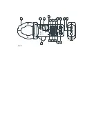
Страница 4: ...s is used to pick up current signal To measure DC AC current conductor must be enclosed by the jaw 2 Transformer Trigger This is used to open the jaw 3 Data Hold Button Once this button is pushed read...

Страница 5: ...econds to disable this function 10 Low Battery Symbol When this symbol appears it means the battery voltage drops below the minimum required voltage Refer to Section V for battery replacement 11 Bargr...

Страница 6: ...uring measurement Press once minimum value shall be displayed and updated Press again maximum value shall be displayed and updated Press again the third push clamp meter return to normal measurement m...

Страница 7: ...Figure 1...

Страница 8: ...ual Overload Indication left most digit blinks Power Consumption 12 mA approx Low battery Indication B Sampling Time 2 times sec display 20 times sec bargraph Dimension 271mm L x 112mm W x 46mm H 10 7...

Страница 9: ...Maximum Altitude 2000 Meter Installation Category EN 61010 1 CAT III 600V Pollution Degree 2 Operating Temperature 4 C to 50 C Operating Humidity less than 85 relative Storage Temperature 20 C to 60 C...

Страница 10: ...esolution 50 60 Hz 40 1KHz Input Impedance 400mV 0 1mV 1 1 1 4V 0 001 1 5 5dgts 2 0 5dgts 5M 40V 0 01V 1 5 5dgts 2 0 5dgts 5M 400V 0 1V 1 5 5dgts 2 0 5dgts 5M 600V 1V 1 5 5dgts 2 0 5dgts 5M 1 400mVAC...

Страница 11: ...to ranging Range Resolution Accuracy of rdg Input Impedance 400mV 0 1mV 1 5 3dgts 10M 4V 0 001V 1 5 3dgts 5M 40V 0 01V 1 5 3dgts 5M 400V 0 1V 1 5 3dgts 5M 600V 1V 1 5 3dgts 5M Overload Protection 800V...

Страница 12: ...g OL Protection 40 400 0 1 1 0 rdg 2dgts 40 0 AC 600V open voltage 0 4V 4 Continuity Built in buzzer sound when measured resistance is less than 40 and sound off when measured resistance is more than...

Страница 13: ...A 0 2000A 1A 1 5 3dgts DC 3000A 2000 2500A 1A 2 0 3dgts DC 3000A 6 ACA Auto ranging Accuracy of rdg Overload Protection Range Resolution 50 60 Hz 40 1KHz 400A 0 1A 1 5 5dgts 2 0 5dgts AC 3000A 0 1000A...

Страница 14: ...5A 600V AC 9 AC DC power 250V max Auto range and Manual Range Resolution Accuracy of reading Overload Protection 40KW 0 01KW 2 5 5dgts 600VAC 400KW 0 1KW 2 5 5dgts 600VAC 600V max Auto range and Manu...

Страница 15: ...11 Temperature Range Resolution Accuracy Overload Protection 50 400 C 0 1 C 1 2 C 600VAC 400 1000 C 1 C 1 2 C 600VAC 50 400 C 0 1 C 1 3 C 600VAC 400 1000 C 1 C 1 3 C 600VAC...

Страница 16: ...tion and to retain the instrument in safe condition 3 1 Preparation and Caution before Measurement 1 If the meter is used near equipment that generates electro magnetic interference the display may be...

Страница 17: ...o be used for a long period of time remove the battery 7 Do not forget to turn off after use 8 Maximum rated voltage to earth for voltage measurement terminals is 600V CAT III THIS INSTRUMENT MUST NOT...

Страница 18: ...3 2 AC Current Measurement...

Страница 19: ...the trigger to open the jaw and fully enclose the conductor to be measured No air gap is allowed between the two half jaws d The clamp meter will automatically select proper range If users want to sel...

Страница 20: ...3 3 DC Current Measurement...

Страница 21: ...lf jaws d The clamp meter will automatically select proper range If users want to select range press the range button before pressing the DC A ZERO button e Read the measured value from the LCD displa...

Страница 22: ...erminals at the same time The output is proportional to the current measured 1mV A c The red terminal is the positive while the black is the negative of the signal d Connect these two terminals to an...

Страница 23: ...leads in PARALLEL to the circuit to be measured d The clamp meter will automatically select proper range If users want to select range press the range button e Read the measured value from the LCD dis...

Страница 24: ...e measured value from the LCD display 3 7 Temperature Measurement Turn the switch to the temperature position Connect the adapter optional to the V terminal Then plug in the K type thermal couple to t...

Страница 25: ...ed Press the zero button for 2 seconds to return to normal mode But this function is disabled if MAX MIN function is enabled Please watch for symbol displayed on LCD 3 11 Holding the LCD Reading Press...

Страница 26: ...RE OPENING THE COVER 4 1 General Maintenance Servicing not covered in this manual should only be performed by qualified personnel Repairs should only be performed by qualified personnel Periodically w...

Страница 27: ...4 2 Battery Installation or Replacement...

Страница 28: ...f and remove the test leads from the clamp meter b Remove the screws of the bottom case c Lift and remove the bottom case d Remove the old battery e Insert new 9V battery f Replace the bottom case and...

Страница 29: ...V Vrieslantlaan 6 3526 AA Utrecht P O Box 7023 3502 KA Utrecht The Netherlands Tel 31 0 30 288 13 11 Fax 31 0 30 289 88 16 E mail sales nieaf smitt nl Internet http www nieaf smitt nl http www nieaf i...

Отзывы: