5 - 4
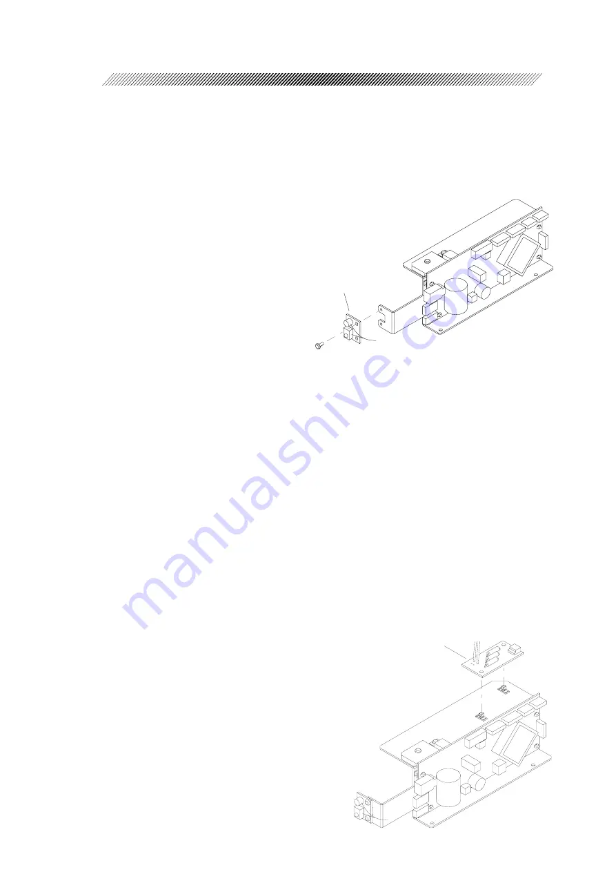
BA02基板
BS3×6
Znc
2
BA02 board
BS3×6
ZnC
2
5.2.2 Replacement of the BA02 board
Replacement part: 33155-BA02
1. Remove the top and front cover ASSYs. (See 5.1.)
2. Disconnect the connector from J7 on the BA01 board.
3. Unscrew BS3 × 6
ZnC
(n=2) to replace the
BA02 board with a new one.
4. Assemble the removed parts in reverse order.
5.2.3 Replacement of the BA14 board
Replacement part: 33155-BA14
[NOTE]
Once the lamp goes on, the device on the BA14 board becomes hot. Do not conduct
work until the device cool down.
1. Remove the top and front cover ASSYs. (See 5.1.)
2. Disconnect J2 connector and EA14 cable connector on the BA01 board.
3. Remove the BA14 board while holding the tops of the two spacers with long-nose pliers
and replace with new one.
* Push the new board into the spacers properly.
4. Assemble the removed parts in reverse order.
BA14基板
BA14 board
Содержание CP-690
Страница 1: ...MCP7 RDA001B E Total Page 70 2006 7 NIDEK AUTOMATIC CHART PROJECTOR Model CP 690 SERVICE MANUAL...
Страница 6: ...1 2...
Страница 8: ...2 2...
Страница 44: ...5 22...
Страница 55: ...INFORMATION 7 7 1 Wiring Diagram Total wiring Diagram EA13 BA14 RESISTOR BOARD 2 2 EA14 CHART LED...
Страница 56: ...7 2 EA01...
Страница 57: ...7 3 EA02...
Страница 58: ...7 4 EA05 EA06 EA13 EA14 BA01 Describe the connector No when assembling Mask side P4 Chart side P6...
Страница 60: ...7 6...
Страница 70: ...9 2...


