


To obtain a perfectly operational and efficient system in terms of the intended
use, the system must first be designed “at the table”, before proceeding to the
operating phases described in this manual. In particular it is fundamental to
establish the number and type of detectors to be used, and their relative loca-
tion according to the specific actions required. To ensure a suitable design, a
layout of the building should be drawn up where the alarm system is to be
installed, specifying the name and position of each device envisaged in the sys-
tem. This layout drawing will be useful and also decisive in the system configu-
ration phase, for example when the name of each device needs to be memo-
rised.
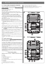
3.1 - How to divide up the home and zones to be protected
The control unit can be programmed to control the entire home concerned or
portions of the latter. For this reason, it is important to first divide up the entire
area covered by the system into three “intervention zones” (zones
A
-
B
-
C
),
assigning each environment to one of the three zones, according to a suitable
and functional logic.
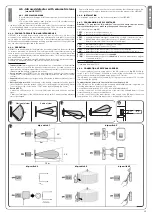
In the case of single buildings, an initial division logic is one of “concentric cir-
cles” (see
fig. 1
). Using this logic, the user can assign, for example, detectors
positioned outside the building to zone A, the perimeter detectors (on doors
and windows) to zone B and the detectors inside the building to zone C. This
division enables, for example, dissuasion of intrusion attempts by means of
voice messages emitted by the siren (in zone A) before entry, or activation of a
DESIGNING AN ALARM SYSTEM
3
siren alarm on the first attempt at break-in via a door or window (in zone B), or
calls to the police forces only when the indoor detectors (in zone C) signal intru-
sion.
Another logic used to divide the areas to be protected is one of “uniform
blocks” (see
fig. 2
). Using this logic, the user can assign, for example, the
rooms on the ground floor to zone A, the rooms on the first floor to zone B, and
the garage to zone C. This division enables, for example, activation of the alarm
in the garage (zone C) while normal activities can continue in the rest of the
house.
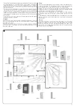
3.2 - Where to position the alarm system components
To decide on the position of the various components of the system, refer to
fig. 3
and also ensure the following conditions:
• Control unit
- The control units operate by transmitting and receiving low power radio sig-
nals (within the limits as specified in the relevant standards), and therefore
must be installed in zones that ensure efficient propagation of the signals.
Therefore avoid alcoves, metal cabinets, posts and walls in reinforced con-
crete; also ensure that there are no large metal surfaces or grids in the vicinity
of the control unit, including those embedded in walls.
- The control unit should be positioned at the centre with respect to the other
devices (see also paragraph 2.1 “Radio transmission inside buildings”).
1
zone
C
zone
B
zone
A
zone
B
zone
A
zone
C
2
4
Содержание HSCU1
Страница 1: ...Nice HSCU1 Instructions and warnings for installation and use Home security control unit 0682 ...
Страница 2: ......
Страница 14: ...12 b a 11 12 13 CRACK CRACK CRACK 14 x 3 x 1 a 15 ...
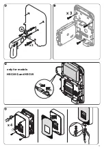
Страница 15: ...18 only for models HSCU1G and HSCU1 x 4 19 x 3 a 16 x 3 17 13 ...
Страница 32: ...42 x 4 44 only for models HSCU1GC and HSCU1C 43 only for models HSCU1G and HSCU1 30 ...
Страница 39: ......


