16
– English
English
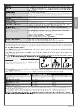
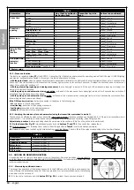
Example of durability calculation: automation of a 3.5 m gate leaf weighing 250 kg, installed in the vicinity of the sea. Table 10 shows the “severity
indices” for this type of installation: 10% (Leaf length), 20% (Leaf weight) and 15% (Presence of dust, sand or salinity). These indices must be added
to each other to obtain the overall severity index, which in this case amounts to 45%. With the value found (45%), check the horizontal axis (severity
index) of Graph 1 and identify the value corresponding to the number of “manoeuvre cycles” our product will be able to perform in its lifespan, equal
to roughly 115,000 cycles.
Table 12
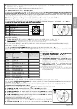
contains useful information to help solve any malfunctions that may occur during installation or in case of a fault.
TABLE 12
Symptoms
Probable cause and possible solution
The radio transmitter does not emit any signal
and the corresponding Led fails to light up
Check the batteries: if they are flat, replace them (consult the transmitter’s instruction manual).
The manoeuvre fails to start and the ECS-
Bus led on the control unit does not flash
• Check that the power
cable is correctly inserted in
the power outlet.
• Check the fuses; if they
have tripped, determine
the cause of the fault and
replace them with others of
the same type: see
Fig. 33
.
fuse
3.15A T
fuse
1A T
33
The manoeuvre fails to start and the auto-
mation’s flashing light is off
Check that the command is actually received. If the command reaches the SbS input, the rel-
evant SbS Led lights up; if a transmitter is used, the ECSBus Led must emit 2 long flashes.
The manoeuvre fails to start and the auto-
mation’s flashing light emits a few flashes
• Check that the Stop input is active (in other words, that the Stop Led is lit). Should this not be
the case, check the device connected to the Stop input.
• The photocells test (which the control unit performs at the start of each manoeuvre) failed:
check the photocells, by verifying their status in
Table 6
.
The manoeuvre starts but is immediately
followed by a reverse run commanded by
the control unit
The programmed “motor force” setting is too low to move the gate. Check whether there are any
obstacles obstructing the gate’s movement and, if necessary, select a higher force as described
in Par. 9.1.1.
The manoeuvre is carried out but the flash
-
ing light is not working
During the manoeuvre, check that there is power on the Flash terminal of the flashing light (being
intermittent, the voltage value is irrelevant: roughly 10–30 VAC); if it is powered, the problem is
due to the lamp not working (consult the flashing light’s instruction manual to replace it).
10
TROUBLESHOOTING


