

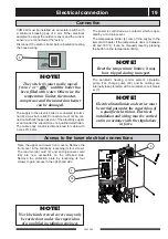


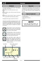


Electrical connection
VVM 240
20
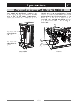
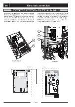
For communications between VVM 240 and FIGHTER
2010 use the supplied modular cable of 15 m. The
modular cable is connected between VVM 240 posi-
tion (4) and FIGHTER 2010 position (44), see the
Installation and Maintenance Instruction. Routing of
the modular cable in FIGHTER 2010 should be done
from below in the cable glands on left-hand side of the
heat pump, seen from the front. Routing of the modu-
lar cable in VVM 240 should be done through the con-
duit, Ø 25, to the left and down on the left front edge.
NOTE!
The sensor and communication cables must
not be routed closed to the power cable.
LEK
4
44
34
FIGHTER 2010
VVM 240
Modular cable between VVM 240 and FIGHTER 2010
2
34
44
4


