23
POOL 11
GB
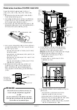
Sensor and communication cables must not
be placed near power cables.
Note!
Install the temperature sensor with cable ties with the
heat conducting paste and aluminium tape.
Then insulate with supplied insulation tape.
LEK
LEK
E
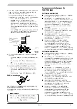
Temperature sensor installation
Pressure/level monitor brine
GT15 External compensation 2
GT16 Pool temperature
X1
-E2
EVB-Card
X4
Return
sensor 1
Flow
sensor 1
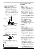
7. The sensors are connected by twin cables (for exam-
ple EKXX or LiYY) as follows for the load monitor
card, EBV– E2 see image below:
Use the following round pin sleeves for splicing be-
tween the 2-cables and sensors GT11 & GT16.
- Connect the sensor used as the flow sensor (GT
11) to terminal –E2:X4:15 and – E2: X4:16 in
the load monitor card’s lower terminal block.
Disconnect the spare sensor from –X204:1 and
– X204:2 (installed on immersion heater, accessed
from the side of the heat pump).
- Connect pool sensor (GT 16) to terminal –
E2: X1:12 and –E2:X1:13 on the load monitor
card’s upper terminal block.
8. Connect Actuator Shuttle valve SV4 as follows:
- Black cable (230v signal) to spring terminal –X6:1
- Brown cable (fixed phase) to spring terminal –X6:2
- Blue cable (zero) to spring terminal –X6:3
9. Connect circulation pump P8 as follows:
- Blue cable (zero) to spring terminal –X6:3
- Yellow/green cable (earth cable) to spring terminal
–X6:4
- Brown cable (phase) to spring terminal –X6:5
Program settings FIGHTER 1220
Program version 1.08 and earlier
■
Select service in menu 8.1.1 to gain access to all the
menus.
■
Activate pool control in menu 9.2.10 by selecting
“ON”. This activates the external circulation pump
and shows the pool setting menus. The pool sensor
must be connected to terminal X1:12-13 otherwise
a sensor alarm is displayed for the pool sensor.
■
Select the desired pool temperature in menu 1.11.1,
this temperature determines when pool heating is
stopped.
■
Select the desired connection difference in menu
1.11.2, this is the difference between the value in
menu 1.11.1 and when pool heating starts.
■
Select the desired pool charging time in menu
1.11.3, this is how long pool heating is permitted to
run. The value can be set between 5 and 60 min-
utes. When pool charging has started, it runs for at
least the time selected in this menu even if a heating
requirement arises.
Program version 1.09 and later
■
Select service in menu 8.1.1 to gain access to all the
menus.
■
Activate pool control in menu 9.2.10 by selecting
“ON”. This activates the external circulation pump
and shows the pool setting menus. The pool sensor
must be connected to terminal X1:12-13 otherwise
a sensor alarm is displayed for the pool sensor.
■
Activate pool control in menu 8.4.4 by selecting
“ON”. This allows the heat pump to heat the pool.
Select ”Off” in menu 8.4.4 to prevent pool heating,
e.g. winter time.
■
Select the desired pool temperature in menu 8.4.1,
this temperature determines when pool heating is
stopped.
■
Select the desired connection difference in menu
8.4.2, this is the difference between the value in
menu 8.4.1 and when pool heating starts.
■
Select the desired pool charging time in menu 8.4.3,
this is how long pool heating is permitted to run.
The value is adjustable between 5 and 60 minutes.
When pool charging has started, it runs for at least
the time selected in this menu even if a heating re-
quirement arises.
Содержание POOL 11
Страница 2: ......
Страница 16: ...14 POOL 11...
Страница 30: ...28 POOL 11...
Страница 44: ...42 POOL 11...
Страница 45: ...43 POOL 11 Elschema SE DE GB Wiring Diagram Elektrischer Schaltplan...
Страница 47: ...45 POOL 11 Elschema Wiring Diagram Elektrischer Schaltplan FIGHTER 1235 1240 1250...
Страница 48: ...46 POOL 11 Elschema Wiring Diagram Elektrischer Schaltplan FIGHTER 1235 1240 1250...
Страница 49: ...47 POOL 11 Elschema Wiring Diagram Elektrischer Schaltplan FIGHTER 1220 1230...
Страница 50: ...48 POOL 11 Elschema Wiring Diagram Elektrischer Schaltplan FIGHTER 1120 1130 1135 1140...
Страница 51: ......


