background image

22

POOL 11

GB

LE

K

LE

K

Electrical connection FIGHTER 1220

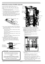
1.  Install the edge protection on the sharp edges, see 

the right image. 

2.   The supplied relay card (-E34) is installed on the exist-

ing relay card (-E29) using plastic turrets, see image 

below. 

3.  Connect the edge connector wiring between the 

supplied relay card (–E34) and relay card (–E29) as 

illustrated below. 

All electrical connections must be carried 

out by an authorised electrician.  

Electrical installation and wiring must be 

carried out in accordance with the stipula-

tions in force.

Note!

Electrical connection

M5, self-tapping 

torx screws

–X6

HAHN


LEK 

Relay card, –E34

Relay card, –E29 

Edge board wiring

4.  Install connection terminals, labels and strain relief 

on the panel. Screw the plate into place with two of 

the accompanying M5 self-tapping screws, see image 

below. 

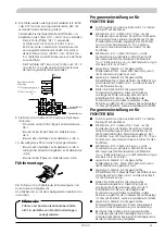
5.   Press the 10-pin edge connector with zero number 

0111 to 0117 on the relay card –E29 as illustrated to 

the right (

Note!

 Observe the guide pin in the edge 

connector). Then install the loose ends as follows: 


-  Blue (single) cable with zero number 0111 to 

spring terminal –X6:3.


-  Brown (single) cable with zero number 0112 to 

spring terminal –X6:1.


-  Brown (single) cable with zero number 0113 to 

spring terminal –X6:2.  


-  Brown cable with zero number 0114 to 0117 is 

installed as follows:


 Flat pin sleeve with cable 0114/0115 to 

– E34:37.


 Flat pin sleeve with cable 0115/0116 to 

– E34:39.


 Flat pin sleeve with cable 0116/0117 to 

– E34:41.


 Finally install the loose end of 0117 in the spare 

place in the spring terminal –X6:2.

 6.  Connect the other single cables as follows: 
 

-  Yellow/green cable with zero number 0108 to 

spare earth connection (-PE) and in spring terminal 

–X6:4. 


-  Brown cable with zero number 0105 to flat pin –

E34:38 and in spring terminal –X6:5. 

-E29 

Relay card

10-pin 

connector

Following cable for Pool 11 used in this kit:  

0105, 0108, 0111 to 0117.

A   B

I II III

I II

I II

5 0 . 0   C

Va r m v a t t e n t e m

p . 1 .0

LEK

A   B

I II III

I II

I II

5 0 . 0   C

Va r m v a t t e n t e m

p . 1 .0

LEK

Electrical 

connection 

–X6

2 x Edge protection

–E29

–E2

–X1

Содержание POOL 11

Страница 1: ...OOL 11 TILL FIGHTER 1130 1135 1230 1235 1250 SE MONTAGEANWEISUNG POOL 11 F R FIGHTER 1120 1140 1220 1240 1250 DE INSTALLATION INSTRUCTIONS POOL 11 FOR FIGHTER 1120 1140 1220 1240 1250 GB GB DE SE ELSC...

Страница 2: ......

Страница 3: ...utegivare UG och framled ningsgivare GT11 Monterad elkassett inkopplas au tomatiskt n r energibehovet verstiger v rmepumpens kapacitet g ller ej poolladdning N r pooltemperaturen sjunkit under inst l...

Страница 4: ...tsen Framledningsgivaren X4 15 16 Poolgivaren X1 12 13 Villkor f r poolladdning Om poolgivaren GT16 inte r ansluten till ts poolladd ningen inte att starta Uppv rmning av poolen prioriteras efter varm...

Страница 5: ...Niv k rl Ing r i F1235 1250 P3 Cirkulationspump 2 Ing r i ESV 21 P8 Cirkulationspump Ing r ej RV Reglerventil SF Smutsfilter Ing r i F1235 1250 SF2 Smutsfilter pool Pahl ns Fabriker Tel 08 59 41 10 50...

Страница 6: ...d nollnummer 0101 och 0110 till flatstiftet E34 37 Brun ensam ledare med nollnummer 0110 till fj derplinten E29 X1b 17 5 Montera kopplingsplintar etikett och dragavlastare p pl ten Skruva fast pl ten...

Страница 7: ...tivera pooluppv rmning i meny 8 4 6 genom att v lja Till Detta till ter att v rmepumpen ska v rma poolen Genom att v lja Fr n i meny 8 4 6 kan pooluppv rmning hindras tex vintertid V lj nskad pooltemp...

Страница 8: ...aren X1 12 13 Villkor f r poolladdning Om poolgivaren GT16 inte r ansluten till ts poolladd ningen inte att starta Uppv rmning av poolen prioriteras efter varmvatten laddning och v rme F ljaktligen p...

Страница 9: ...1 NK Niv k rl Ing r i F1230 P3 Cirkulationspump 2 Ing r i ESV 21 P8 Cirkulationspump Ing r ej RV Reglerventil SF Smutsfilter Ing r i F1230 SF2 Smutsfilter pool Pahl ns Fabriker Tel 08 59 41 10 50 SV3...

Страница 10: ...ensam ledare med nollnummer 0112 till fj derplint X6 1 Brun ensam ledare med nollnummer 0113 till fj derplint X6 2 Bruna ledare med nollnummer 0114 till 0117 monteras enligt f ljande Flatstifthylsa m...

Страница 11: ...tivera poolstyrning i meny 9 2 10 genom att v lja Till Detta aktiverar yttre cirkulationspump samt visar poolinst llningsmenyerna Poolgivare m ste vara ansluten p plint X1 12 13 annars visas givar lar...

Страница 12: ...n inte att starta Uppv rmning av poolen prioriteras efter varmvatten laddning och v rme F ljaktligen p b rjas endast pool laddningen d inget v rme eller varmvattenbehov finns D poolladdning har p b rj...

Страница 13: ...3 Cirkulationspump 2 Ing r i ESV 21 P8 Cirkulationspump Ing r ej RV Reglerventil SF Smutsfilter Ing r i F1130 1135 SF2 Smutsfilter pool Pahl ns Fabriker Tel 08 59 41 10 50 SV3 Shuntventil Ing r i ESV...

Страница 14: ...6 De vriga enskilda ledarna anslutes enligt f ljande Bl ledare med nollnummer 0118 mellan skruv plint X6 18 till fj derplinten X6 3 Brun ledare med nollnummer 0119 mellan skruv plint X6 19 till fj de...

Страница 15: ...fferans i meny 1 11 2 detta r differensen mellan v rdet i meny 1 11 1 och n r pooluppv rmning startas V lj nskad poolladdningstid i meny 1 11 3 detta r under hur l ng tid poolv rmning r till tet att p...

Страница 16: ...14 POOL 11...

Страница 17: ...p is controlled by the outdoor sensor and flow sensor The installed immersion heater is connected automatically when the energy requirement exceeds the heat pump capacity not during pool charging When...

Страница 18: ...pump to out on the heating circuit The flow line sensor X4 15 16 The pool sensor X1 12 13 Conditions for pool charging If the pool sensor is not connected pool charging is not permitted to start Heati...

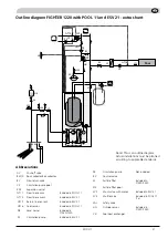
Страница 19: ...essel Included in F1240 1250 P3 Circulation pump Included in ESV 21 P8 Circulation pump Not included RV Control valve SF Particle filter Included in F1240 1250 SF2 Particle filter pool SV3 Shunt valve...

Страница 20: ...39 Brown cable with zero number 0101 and 0110 to flat pin E34 37 Brown single cable with zero number 0110 to spring terminal E29 X1b 17 5 Install connection terminals labels and strain relief on the...

Страница 21: ...eating in menu 8 4 6 by selecting ON This allows the heat pump to heat the pool Select Off in menu 8 4 6 to prevent pool heating e g winter time Select the desired pool temperature in menu 8 4 1 this...

Страница 22: ...ow line sensor X4 15 16 The pool sensor X1 12 13 Conditions for pool charging If the pool sensor is not connected pool charging is not permitted to start Heating the pool is prioritised after hot wate...

Страница 23: ...sel Included in F1240 1250 P3 Circulation pump Included in ESV 21 P8 Circulation pump Not included RV Control valve SF Particle filter Included in F1240 1250 SF2 Particle filter pool SV3 Shunt valve w...

Страница 24: ...lustrated to the right Note Observe the guide pin in the edge connector Then install the loose ends as follows Blue single cable with zero number 0111 to spring terminal X6 3 Brown single cable with z...

Страница 25: ...is activates the external circulation pump and shows the pool setting menus The pool sensor must be connected to terminal X1 12 13 otherwise a sensor alarm is displayed for the pool sensor Select the...

Страница 26: ...s not connected pool charging is not permitted to start Heating the pool is prioritised after hot water charging and heating Consequently pool charging only starts when there is no heating or hot wate...

Страница 27: ...P3 Circulation pump Included in ESV 21 P8 Circulation pump Not included RV Control valve SF Particle filter Included in F1120 1140 SF2 Particle filter pool SV3 Shunt valve with motor Included in ESV 2...

Страница 28: ...ng terminal X6 2 Flat pin sleeve with cable 0121 0122 to E34 37 Flat pin sleeve with cable 0122 0123 to E34 39 Single flat pin sleeve with cable 0123 to E34 41 6 Connect the other single cables as fol...

Страница 29: ...this is the difference between the value in menu 1 11 1 and when pool heating starts Select the desired pool charging time in menu 1 11 3 this is how long pool heating is permitted to run The value c...

Страница 30: ...28 POOL 11...

Страница 31: ...und Vorlauff hler GT11 gesteuert Die eingebaute Elektroheizkassette wird automatisch zugeschaltet wenn der Energiebedarf die Leistung der W rmepumpe bersteigt nicht bei Poolerw rmung Wenn die Pooltem...

Страница 32: ...X4 15 16 Poolf hler X1 12 13 Bedingungen f r die Poolerw rmung Wenn der Poolf hler GT16 nicht angeschlossen ist kann die Poolerw rmung nicht gestartet werden Die Brauchwasser und W rmebereitung erh lt...

Страница 33: ...Lieferumfang von F1240 1250 enthalten SF2 Schmutzfilter Pool SV3 Mischventil Im Lieferumfang von ESV21 enthalten SV4 Umschaltventil Im Lieferumfang von POOL 11 enthalten 1 St S V Sicherheitsventil UG...

Страница 34: ...er 0100 und 0101 an Flachstift E34 39 Braune Leiter mit Nullnummer 0101 und 0110 an Flachstift E34 37 Brauner Leiter einzeln mit Nullnummer 0110 an Federklemme E29 X1b 17 5 Befestigen Sie Anschlusskle...

Страница 35: ...Aus in Men 8 4 6 aus um die Poolerw rmung zu blockieren z B im Winter Legen Sie in Men 8 4 1 die gew nschte Pooltemperatur fest Dieser Wert bestimmt wann die Poolerw rmung gestoppt wird Legen Sie in...

Страница 36: ...edingungen f r die Poolerw rmung Wenn der Poolf hler GT16 nicht angeschlossen ist kann die Poolerw rmung nicht gestartet werden Brauchwasserbereitung und Heizung erhalten Vorrang vor der Poolerw rmung...

Страница 37: ...m Lieferumfang von ESV21 enthalten SV4 Umschaltventil Im Lieferumfang von POOL 11 enthalten 1 St S V Sicherheitsventil UG Au enf hler Im Lieferumfang von F1240 1250 enthalten VX Poolw rme bertrager Pr...

Страница 38: ...is 0117 auf die Relaiskarte E29 siehe Abbildung rechts Hinweis Beachte Steg im Eckkantenstecker Bringen Sie danach die losen Enden wie folgt an Blauer Leiter einzeln mit Nullnummer 0111 an Federklemme...

Страница 39: ...entsteht Ab Programmversion 1 09 Durch Auswahl von Service in Men 8 1 1 erhalten Sie Zugriff auf alle Men s W hlen Sie Ein in Men 9 2 10 aus um die Poolsteuerung zu aktivieren Dadurch wird die exter n...

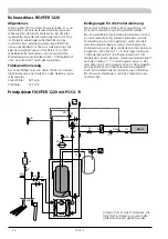
Страница 40: ...n Fr hling Herbst und Auto Winter durch das Heizsystem F hlerpositionierung Der Vorlauff hler muss von seiner Position im Inneren der W rmepumpe nach au en an den Heizkreis umge setzt werden Vorlauff...

Страница 41: ...ler 2 Im Lieferumfang von ESV21 enthalten GT16 Poolf hler Im Lieferumfang von POOL 11 enthalten NK Niveaugef Im Lieferumfang von F1120 1140 enthalten P3 Umw lzpumpe 2 Im Lieferumfang von ESV21 enthalt...

Страница 42: ...gt montiert Loses Ende von 0121 an Federklemme X6 2 Flachstifth lse mit Leiter 0121 0122 an E34 37 Flachstifth lse mit Leiter 0122 0123 an E34 39 Einzelne Flachstifth lse mit Leiter 0123 an E34 41 6 D...

Страница 43: ...d dem Startwert f r die Poolerw rmung Stellen Sie in Men 1 11 3 die gew nsch te Poolerw rmungszeit ein Dieser Wert gibt an wie lange die Poolerw rmung aktiv sein darf Einstellbereich 5 60 min Nach Beg...

Страница 44: ...42 POOL 11...

Страница 45: ...43 POOL 11 Elschema SE DE GB Wiring Diagram Elektrischer Schaltplan...

Страница 46: ...40 1250 SE Kompressor GB Compressor DE Verdichter SE Uttag f r versioner med emlajerade k rl Inte installerad i alla mo deller GB O utlet for enamelled vessel Not installed in all models DE A nschluss...

Страница 47: ...45 POOL 11 Elschema Wiring Diagram Elektrischer Schaltplan FIGHTER 1235 1240 1250...

Страница 48: ...46 POOL 11 Elschema Wiring Diagram Elektrischer Schaltplan FIGHTER 1235 1240 1250...

Страница 49: ...47 POOL 11 Elschema Wiring Diagram Elektrischer Schaltplan FIGHTER 1220 1230...

Страница 50: ...48 POOL 11 Elschema Wiring Diagram Elektrischer Schaltplan FIGHTER 1120 1130 1135 1140...

Страница 51: ......

Страница 52: ...Fax 97 17 29 33 E mail info volundvt dk www volundvt dk NIBE Systemtechnik GmbH Am Reiherpfahl 3 29223 Celle Tel 05141 7546 0 Fax 05141 7546 99 E mail info nibe de www nibe de CH NIBE W rmetechnik AG...

Отзывы: