©
National Instruments
27
NI WSN-3214 User Guide and Specifications
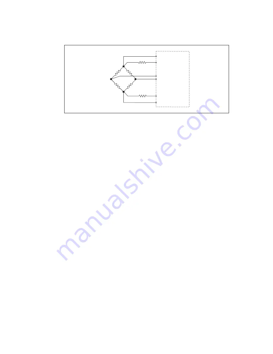
Figure 25.
Connecting Remote Sense Wires to the NI WSN-3214
The actual bridge excitation voltage is smaller than the voltage at the EX+ and EX– leads. If you do not
use remote sensing of the actual bridge voltage, the resulting gain error is:
for half-bridge sensors and
for full-bridge sensors.
If you connect the remote sense signals directly to the bridge resistors, the NI WSN-3214 senses the
actual bridge voltage and adjusts the excitation voltage to compensate for the gain errors caused by the
resistance of the EX+ and EX– leads. There is a limit to the amount of resistance that can be
compensated for, which is:
For example, if you are using a 350
Ω
full-bridge, the amount of resistance that can be compensated
for is
Shunt Calibration
Remote sensing corrects for resistances from the EX pins on the NI WSN-3214 to the sensor, and shunt
calibration corrects for these errors and for errors caused by wire resistance within an arm of the bridge.
Shunt calibration is most useful with quarter-bridge sensors because there may be significant resistance
in the wiring to the active resistor in the bridge. Refer to Figure 26 for a diagram of this setup
.
The
NI WSN-3214 shunt calibration circuitry consists of a precision resistor and a software-controlled
switch. Refer to the software help for information about enabling the shunt calibration switch for the
NI WSN-3214.
EX+
EX–
R
S
+
R
S
–
R
b
ridge
R le
a
d
R le
a
d
R
b
ridge
R
b
ridge
R
b
ridge
NI W
S
N-
3
214
AI–
AI+
R
lead
R
bridge
---------------------
2
R
lead
⋅
R
bridge
----------------------
100 mV
Excitation current
-------------------------------------------
100 mV
5.7mA
(
)
---------------------
17
Ω
=


