


©
National Instruments Corporation
5
NI PXIe-1435 User Guide
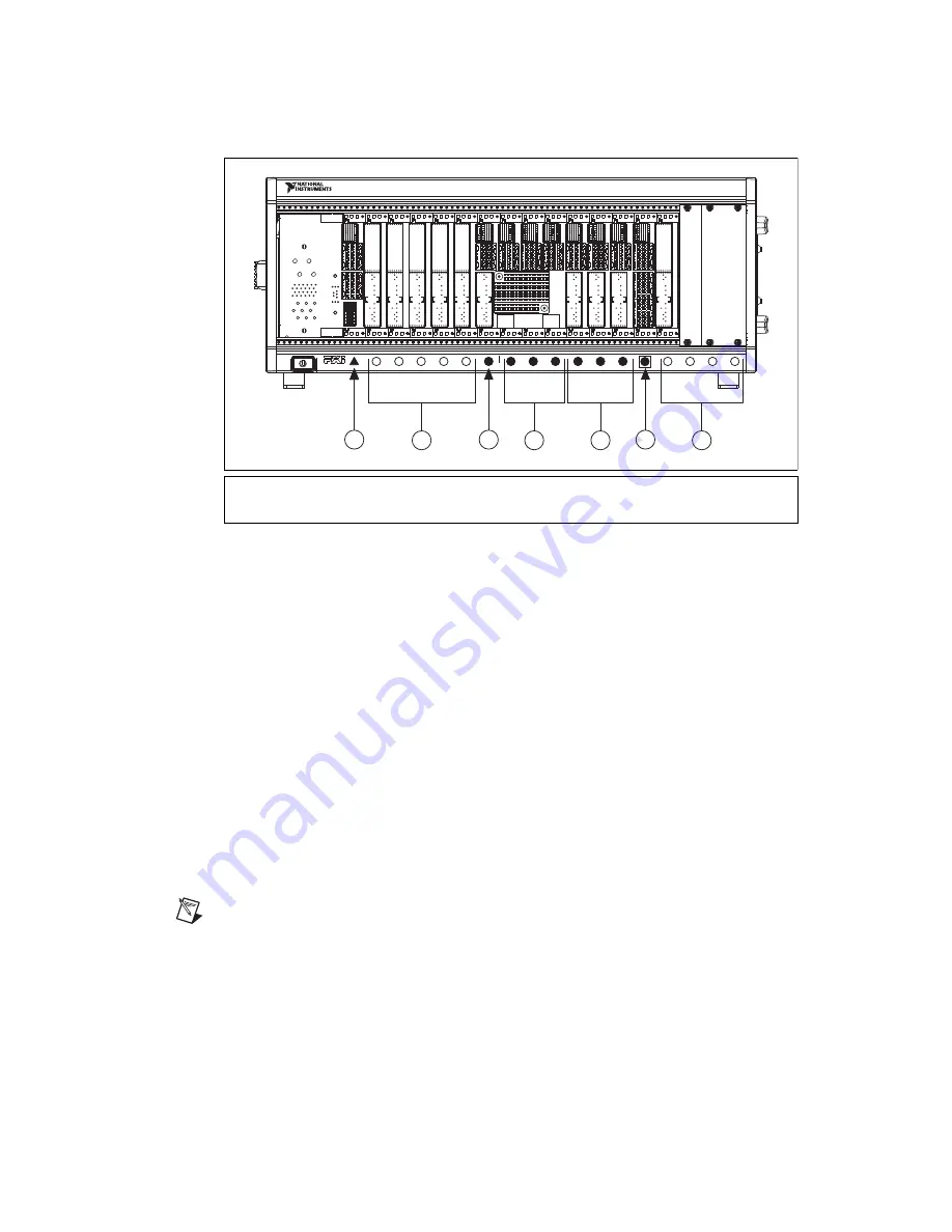
Figure 1.
Symbols for PXI Express/PXI Express Hybrid/PXI Slots
4.
Remove the filler panel and touch any metal part of the chassis to discharge static electricity.
5.
Place the module edges into the module guides at the top and bottom of the slot.
6.
Slide the module along the guides until it reaches the rear connector, then seat the module by
pushing the front panel until it is flush with the front panel of the chassis.
7.
Secure the device front panel to the chassis front panel mounting rail using the front-panel
mounting screws.
8.
Connect the Camera Link cable(s) to the Camera Link camera. Refer to the camera manufacturer
documentation for specific instructions about how to connect the cable to your camera.
9.
Connect the Camera Link cable to the Camera Link connector on the NI 1435 front panel.
10. Plug in and power on the PXI Express chassis.
Confirm the Device is Recognized
To confirm that the device is recognized, complete the following additional steps:
1.
Select
Start»All Programs»National Instruments»Measurement & Automation
to open
Measurement & Automation Explorer (MAX).
2.
Expand
Devices and Interfaces
.
3.
Verify that the device appears under
Devices and Interfaces»NI-IMAQ Devices
.
Note
You can use MAX to maintain trigger reservations for each of your PXI Express chassis. Refer
to
Configuring PXI Triggers
in the
Measurement & Automation Explorer Help
for more information.
1
PXI Express System Controller Slot
2
PXI Peripheral Slots
3
PXI Express Hybrid Peripheral Slots
4
PXI Express Peripheral Slots
5
PXI Express System Timing Slot
18
17
16
15
1
3
12
11
10
9
8
7
6
5
4
3
2
NI PXIe-1065
3
1
H
14
H
H
H
2
2
3
4
5
1
Artisan Technology Group - Quality Instrumentation ... Guaranteed | (888) 88-SOURCE | www.artisantg.com


