


©
National Instruments Corp.
5
cFP-RLY-423
The cFP-RLY-423 has four independent Form C electromechanical
relays. The relays are break-before-make. At power-up, all relays
are in the NC state. Turning the relay channel on breaks the NC–IC
connection and makes the NO–IC connection. Each relay can be
controlled independently, or all relays can change states
simultaneously.
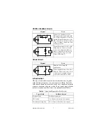
There is an effective resistance of up to 200 m
Ω
between IC and
NC or NO. This resistance causes a voltage drop.
1
For example, if
the current is 1.5 A, the voltage drop across the IC and NC or NO
terminals can be as high as 0.3 V.
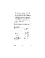
The amount of current the relay can switch depends on the voltage,
the type of load, and the ambient temperature. Refer to the
section for more information.
Protecting Contacts from Inductive Loads
When inductive loads are connected to the relays, a large
counter-electromotive force can occur at relay switching time
because of the energy stored in the inductive load. These flyback
voltages can severely damage the relay contacts and greatly
shorten the life of the relay.
It is best to limit flyback voltages by installing a flyback diode
across an inductive DC load or a metal oxide varistor (MOV)
across an inductive AC load. Refer to the
section for more information.
In addition, the cFP-RLY-423 has internal protection MOVs to
prevent excessively high voltage from being applied across the
contacts. Each channel contains two MOVs: one between NC and
IC and one between NO and IC. However, National Instruments
recommends installing a protection circuit across any inductive
load, as close as possible to the load. The flyback protection MOVs
cause a small leakage current, which is detailed in the
section.
1
At the end of relay life, the path resistance rises rapidly above 1
Ω
.


