background image

GETTING STARTED GUIDE

Ettus USRP X410

1 MHz to 7.2 GHz, 400 MHz Bandwidth, GPS-Disciplined OCXO,
USRP Software Defined Radio Device

This document explains how to install, configure, and test the Ettus USRP X410 Software
Defined Radio Device.

The Ettus USRP X410 can send and/or receive signals for use in various communications
applications. You can use NI-USRP or the USRP Hardware Driver (UHD) to program the
device.

Contents

Unpacking the Kit..................................................................................................................... 1

Verifying the Kit Contents................................................................................................ 2

Additional Items for Device Set-Up......................................................................................... 2
Verifying the System Requirements..........................................................................................3
Ettus USRP X410 Front Panel, Back Panel, and LEDs ...........................................................3
Selecting Your Driver................................................................................................................6
NI-USRP................................................................................................................................... 8

Setting Up the Device....................................................................................................... 8
Installing the Software.................................................................................................... 11
Programming the Device.................................................................................................11

UHD........................................................................................................................................ 16

Setting Up the Device..................................................................................................... 16
Installing the Software.................................................................................................... 18
Programming the Device................................................................................................ 18

NI Services..............................................................................................................................19

Unpacking the Kit

Notice


To prevent electrostatic discharge (ESD) from damaging the device, ground

yourself using a grounding strap or by holding a grounded object, such as your
computer chassis.

1.

Touch the antistatic package to a metal part of the computer chassis.

2.

Remove the device from the package and inspect the device for loose components or any
other sign of damage.

Notice


Never touch the exposed pins of connectors.

Содержание Ettus USRP X410

Страница 1: ...ing the System Requirements 3 Ettus USRP X410 Front Panel Back Panel and LEDs 3 Selecting Your Driver 6 NI USRP 8 Setting Up the Device 8 Installing the Software 11 Programming the Device 11 UHD 16 Setting Up the Device 16 Installing the Software 18 Programming the Device 18 NI Services 19 Unpacking the Kit Notice To prevent electrostatic discharge ESD from damaging the device ground yourself usin...

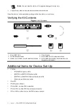
Страница 2: ... SENSITIVE ESD SENSITIVE 2 Channel RF 1 MHz to 7 2 GHz Transceiver 400 MHz BW 2 Channel RF 1 MHz to 7 2 GHz Transceiver 400 MHz BW 1 2 4 3 1 Ettus USRP X410 2 CAT 5E Ethernet Cable 3 USB A m to USB C m with Jack Screw Cable 4 Power Supply 5 Ettus USRP X410 Documentation Note 6 Ettus USRP X410 Safety Environmental and Regulatory Information Additional Items for Device Set Up Cables PCIe MXI express...

Страница 3: ...stem and supported application development environments ADEs The NI USRP Readme is available online on the driver software download page or at ni com manuals The UHD Readme is available on The USRP Hardware Driver Repository Ettus USRP X410 Front Panel Back Panel and LEDs Figure 2 Front Panel TX RX 0 TX RX 0 TX OUTPUT MAX 15 dBm RX INPUT MAX 20 dBm ALL RF PORTS 50 Ω RX 1 RX 1 DB 1 DB 0 RF 0 RF 1 T...

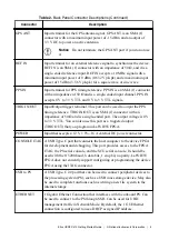
Страница 4: ...onnectors Output voltage can be configured per individual connector either 1 8 V default 2 5 V or 3 3 V Figure 3 Back Panel CONSOLE ETHERNET POWER USB to PS GPS ANT IN 15 dBm MAX OUT 3 3 V DC PPS IN 0 0 QSFP28 iPass zHD 1 1 3 3 V 3 V MIN 5 V MAX TRIG IN OUT 3 3 V 2 V MIN 5 V MAX REF IN 15 dBm MAX 10 100 1000 12 V DC 16A MAX RESET LED 1 LED 0 PWR LED 2 JTAG XXXXXXX XX AIRFLOW XXXXXXX EXHAUST Table ...

Страница 5: ...e of 50 Ω and is a single ended port The output voltage is 0 V to 3 3 V TTL You can also use this port as a triggered output TRIG OUT that you program in LabVIEW FPGA POWER Input that accepts a 12 V 5 16 A external DC power connector CONSOLE JTAG A USB Type C port that connects the host computer to the device FPGA for development and debugging This port provides access to the FPGA JTAG the PS seri...

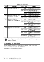
Страница 6: ...is read or write activity on the eMMC Solid There is read or write activity on the eMMC PWR Indicates the power state of the device OFF The device is powered off Green Solid The device is powered on and the power is good Red Solid The device is in a power error state Amber Solid The device is powered off and the power is good Note The previous table describes default LED settings LED functionality...

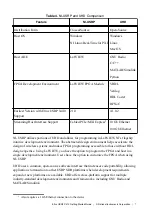
Страница 7: ...environment helps accelerate the design of wireless systems and makes FPGA programming accessible to those without HDL design expertise Using LabVIEW you have the option to program the FPGA and host in a single development environment Users have the option to customize the FPGA when using NI USRP UHD uses a common open source software interface that increases code portability allowing applications...

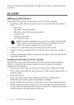
Страница 8: ...ts required for your project to the front panel terminals of the Ettus USRP X410 Installing the Modules into the Chassis Install the PXIe 8881 or other PXI controller in the first slot of your chassis and then the PXIe 8394 or other PXI bus extension module in a slot to the right of the controller by completing the following steps 1 Ensure the AC power source is connected to the chassis before ins...

Страница 9: ...el to the chassis using the front panel mounting screws Note Tightening the top and bottom mounting screws increases mechanical stability and also electrically connects the front panel to the chassis which can improve the signal quality and electromagnetic performance 11 Complete steps 5 through 10 for the PXI controller and PXI bus extension module 12 Cover all empty slots using either filler pan...

Страница 10: ...XX EXHAUST PWR LINK 4 3 2 1 PXIe 8394 MXI Express PS TEMP FANS PXIe 8881 Embedded Controller USER1 USER2 DRIVE PWR OK FAULT TRIG RESET 10 100 1000 GPIB 10 100 1000 ACT LINK ACT LINK 0 1 1 2 1 8 6 5 7 3 4 2 7 1 Ettus USRP X410 2 PXIe Chassis 3 PXIe 8881 or other PXI Controller 4 PXIe 8394 or other PXI Bus Extension Module 5 Network Switch optional 6 PCIe MXI Express Cable 7 CAT 5E Ethernet Cable 8 ...

Страница 11: ...a wall outlet Press the power button on the front of your device 3 Power on the chassis and network switch Installing the Software You must be an Administrator to install NI software on your computer 1 Install your ADE LabVIEW 2 Download the driver software installer from ni com downloads NI Package Manager downloads with the driver software to handle the installation Refer to the NI Package Manag...

Страница 12: ...the combination of numbers and letters following serial as your unique serial number The serial number is also printed on a label on the bottom of your device Use the IP address following addr to identify your device in step 7 3 Use an SSH connection to access your device s management console a To open an SSH connection use your unique serial number to run the command ssh root ni x4xx serial Runni...

Страница 13: ...o update the SSH security fingerprint of your device run the command ssh keygen R ni x4xx serial c To reconnect to the management console run the command ssh root ni x4xx serial d Type yes and press Enter if you are asked whether you want to continue connecting e To verify that you are using the updated file system run the command cat etc mender artifact_info The resulting output contains the vers...

Страница 14: ...Chassis tree item MAX lists all modules installed in the chassis Your default names may vary Note If you do not see your module listed press F5 to refresh the list of installed modules If the module is still not listed power off the system ensure the module is correctly installed and restart 4 Record the identifier MAX assigns to the hardware Use this identifier to reference the Ettus USRP X410 Ve...

Страница 15: ...ples Note You can access additional examples from the Code Sharing Community at ni com usrp Note The NI Example Finder does not include NI USRP examples Troubleshooting If an issue persists after you complete a troubleshooting procedure search our KnowledgeBase for additional information our technical support engineers create as they answer common user questions and resolve unexpected issues Why C...

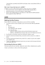
Страница 16: ...wing additional items Host PC Network switch CAT 5E Ethernet Cable optional One of the following QSFP28 to QSFP28 Ethernet cable and 100 Gb Ethernet network card QSFP28 to 4xSFP28 Ethernet breakout cable and 10 Gb Ethernet network card 2 Set all items on a flat surface near power outlets and a modem or router 3 Follow the instructions included with your network switch to connect it to a modem or r...

Страница 17: ...4 100 G Ethernet Network Card 5 10 G Ethernet Network Card 6 QSFP28 to QSFP28 Ethernet Cable optional 7 CAT 5E Ethernet Cable optional 8 CAT 5E Ethernet Cable optional 9 QSFP28 to 4xSFP28 Ethernet Breakout Cable optional 10 Power Supply Table 7 Ettus USRP X410 Connections UHD Connector Type Connection 1 Connection 2 Label in Figure QSFP28 to QSFP28 Ethernet Cable Ettus USRP X410 QSFP28 0 Port 100 ...

Страница 18: ...he power supply to the Ettus USRP X410 2 Plug the power supply into a wall outlet Press the power button on the front of your device 3 Power on the host PC and network switch Installing the Software To program your device with UHD install UHD on your host computer Navigate to the installation guide that applies to your operating system Linux ni com r linuxuhdinstall OS X ni com r osxuhdinstall Win...

Страница 19: ... support to find support resources including documentation downloads and troubleshooting and application development self help such as tutorials and examples Visit ni com services to learn about NI service offerings such as calibration options repair and replacement Visit ni com register to register your NI product Product registration facilitates technical support and ensures that you receive imp...

Страница 20: ...ULAs and third party legal notices in the readme file for your NI product Refer to the Export Compliance Information at ni com legal export compliance for the NI global trade compliance policy and how to obtain relevant HTS codes ECCNs and other import export data NI MAKES NO EXPRESS OR IMPLIED WARRANTIES AS TO THE ACCURACY OF THE INFORMATION CONTAINED HEREIN AND SHALL NOT BE LIABLE FOR ANY ERRORS...

Отзывы: