16
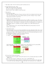
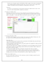
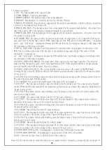
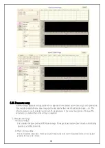
5. Time display column - Shows the instant action time of pressing (unit: sec)
6. Pressing quantity data display column -
CPBPV - The total press points on the backplane
Q'ty-
Shows the number of completed PCB board
Number of repeat - Shows the number of repeat press points
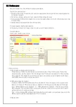
7. Abnormal item -
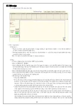
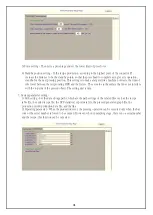
1) Press head status column -
If the safety handle is not pulled down, the press head does not drop to the red display (means the press head
does not reach the position). After the safety handle is pulled, the position is changed to the green display
(means the press head has been positioned).
2) Original point return (OPR) status display -
During the production by the recipe, the press head will force the OPR and confirm the accuracy of the distance
setting. However, the OPR will not be performed if the safety handle is not pulled to allow the press head to be
positioned. Therefore, if the calibration is not performed, the field is red (OPR calibration is not completed), the
OPR calibration operation is completed, and the field is displayed in green (OPR calibration has been
completed).
Note - Although the speed is slow when performing OPR calibration, please keep people away from the
machine to prevent injuries.
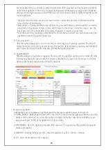
3) Abnormal item column -
When an abnormality occurs, it corresponds to the abnormal item column, and abnormal statuses such as "time",
"stress", and "distance" are displayed as red abnormalities. The pressing parameter message stays at the current
pressing sequence number. After confirming the status of the press, and selecting the abnormality, select one of
the following steps (continued or repeated) for subsequent operations.
1) “Continue” - Perform the next pressing procedure.
2) “Retry”- Repeat the current procedure.
If the abnormal item is "Interrupt", it will be displayed as a red abnormal state, but its exception handling
block is "ALARM RESET", and it must be eliminated to release the procedures.
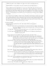
4) The reset steps of various work interrupt -
1) The press head is not in its position - Pull the safety handle to the lower positioning point and press ALARM
RESET again.
2) The safety sensor is triggered - Eliminate the cause and press ALARM RESET again.
3) The servo upper and lower limits are triggered - In manual mode, press to rise the Z axis (lower limit trigger)
or lower the Z axis (upper limit trigger) to make the press head away from the limit sensor to eliminate the
Содержание LPM3
Страница 1: ...1 LPM3 Manual Company Nextronics Date 2018 04 16 Version LPM3 A0 ...
Страница 36: ......

