background image


LED Descriptions 

The LEDs on the front panel provide users with switch status checking and 
monitoring. There are three types of LEDs as follows: 


System LED


indicatesif the switch is powered up correctly or not, or, indicates if 
there is a system alarm triggered for troubleshooting. 


Mode LEDs


indicates the mode of all ports on the switch. Users can press the 
Mode button sequentially to switch amongthe two different modes 
(Link/Activity/Speed mode and PoE mode). 


Port Status LEDs    

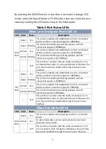
indicates the current status of each port. Users can check these LEDs 
to understand the port status in different modes, after changing the 
mode by pressing Mode button. 

The following table details the functions and descriptions of variousLED 
indicators. 


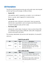
Table1:SystemLED 

LED 

Color 

State 

Description 

System 

Green 

On 

The switch is powered ON correctly. 

Off 

The switch is not receiving power. 

Red 

On 

An abnormal state, such as exceeding 
operating temperature range, has been 
detected in the switch. 


Table 2:ModeLEDs 

LED 

Color 

State 

Description 

Link/Act/Speed 

Green 

On 

The Port Status LEDs are displaying link 
status, network activity and speed of each 
port. 

PoE 

Green 


On 

The RJ45 Port Status LEDs are displaying 
PoE powering status of each port. 

Содержание POE2429L2-370

Страница 1: ...i NEXT POE2429L2 370 Web Smart GbE PoE Switch Quick Installation and Initial Configuration ...

Страница 2: ...er 2 Installing the Switch 5 Package Contents 5 Mounting the Switch in a 19 inch Rack 5 Mounting the Switch on Desk or Shelf 6 Connecting the AC Power Cord 7 Installing SFP Modules 7 Chapter 3 Initial Configuration of Switch 9 Initial Switch Configuration Using Web Browsers 9 Initial Switch Configuration Procedure 9 Chapter 4 Troubleshooting 12 ...

Страница 3: ...uide users can perform the following tasks To check the switch status by reading the LED behavior To reset the switch or to restore the switch to factory defaults To install the switch To use a Web browser to initially configure the switch To troubleshoot the switch Front View of the Switch Figure 1 Front panel of the switch Rear View of the Switch Figure2 Rear panel of the switch ...

Страница 4: ...s of each port Users can check these LEDs to understand the port status in different modes after changing the mode by pressing Mode button The following table details the functions and descriptions of variousLED indicators Table1 SystemLED LED Color State Description System Green On The switch is powered ON correctly Off The switch is not receiving power Red On An abnormal state such as exceeding ...

Страница 5: ...ve been disabled through the switch user interface SFP Ports Green On The port is enabled and established a link to connected device and the connection speed is 1000Mbps Green Blinking The port is transmitting receiving packets and the connection speed is 1000Mbps Amber On The port is enabled and established a link to connected device and the connection speed is 100Mbps Amber Blinking The port is ...

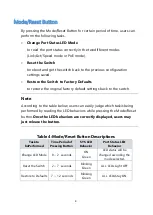
Страница 6: ...t settings back to the switch Note According to the table below users can easily judge which taskisbeing performed by reading the LED behaviors while pressing the Mode Reset button Once the LED behaviors are correctly displayed users may just release the button Table 4 Mode Reset Button Descriptions Task to bePerformed Time Period of Pressing Button SYS LED Behavior Port Status LED Behavior Change...

Страница 7: ...sed with outdoor devices such as outdoor IP cameras or outdoor WiFi APs then users are strongly suggested to install a surge protector or surge suppressor in order to protect the switch Mounting the Switch in a 19 inch Rack Step1 Attach the mounting brackets to both sides of the chassis Insert screws and tighten then with a screwdriver to secure the brackets Figure 3 Attaching Brackets to the Swit...

Страница 8: ...he rack posts Step 3 Attach the brackets to the posts Insert screws and tighten them Figure 4 Attaching Brackets to the Rack Post Mounting the Switch on Desk or Shelf Step1 Verify that the workbench is sturdy and reliably grounded Step2 Attach the four adhesive rubber feet to the bottom of the switch Figure 5 Attaching the Rubber Feet ...

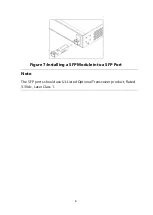
Страница 9: ... AC power outlet Step 3 Check the SYS LED If it is ON the power connection is correct Figure 6 Connecting AC power cord Installing SFP Modules You can install or remove a mini GBIC SFP module from a SFP port without having to power off the switch Step1 Insert the module into the SFP port Step2 Press firmly to ensure that the module seats into the connector ...

Страница 10: ...8 Figure 7 Installing a SFP Module into a SFP Port Note The SFP ports should use UL Listed Optional Transceiver product Rated 3 3Vdc Laser Class 1 ...

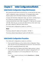
Страница 11: ...the switch s default IP address as shown below The initial switch configuration procedure is as follows Note The factory default IP address of the switch is 192 168 1 1 The factory default Subnet Mask of switch is255 255 255 0 Initial Switch Configuration Procedure The initial switch configuration procedure is as follows 1 Power up the PC that you will use for the initial configuration Please make...

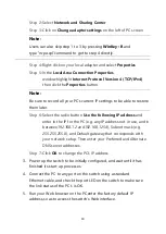
Страница 12: ...he radio button Use the following IP address and enter in the IP for the PC e g any IP address not in use and in between192 168 1 2 and192 168 1 254 Subnet mask e g 255 255 255 0 and Default gateway that corresponds with your network setup Then enter your Preferred and Alternate DNS server addresses Step 7 Click OK to change the PC s IP address 3 Power up the switch to be initially configured and ...

Страница 13: ...orm the following steps Refresh the web page Check to see if there is an IP conflict issue Cleanbrowser cookies and temporary internet files Check your PC settings again and repeat step 2 6 Enter the factory default username and password in login page Click Login to log into the switch Note The factory default Username of the switch isadmin There is no factory default Password of the switch ...

Страница 14: ...e corresponding actions to resolve Port Status LED is Off in the Link Act Speed Mode The port is not connected or the connection is not working 1 Check if the cable connector plug is firmly inserted and locked into the port at both the switch and the connected device 2 Make sure the connected device is up and running correctly 3 If the symptom still exists try different cable or different port in ...

Страница 15: ...경우 보증기간은 제품에 표시된 제조년월일을 기준으로 합니다 B 본 제품은 제조년월로부터 6개월 내에 판매 되어야 하며 제조년월로부터 6개월이 지난 다음 판매된 경우 보증 기간은 제조년월로부터 24개월로 처리가 됩니다 C USB케이블 전원공급장치 아답타 등의 유상구입은 제품보증기간 내에만 가능하나 재고가 있으면 제품보증기간이 지나도 구입 가능 합니다 D 천재지변으로 인한 것은 유상수리입니다 E 소비자과실로 인한 고장은 무상수리가 되지 않을 수도 있습니다 F 본 제품의 A S는 소비자가 A S센터 고객지원센타 를 방문하는 것을 원칙으로 합니다 G 우편 택배 을 통한 A S접수 시 제품을 당사로 보내는 것은 소비자의 책임이며 당사에서 소비자에게 보내는 것은 당사의 책임입니다 본 설명서에 사용된 특정 단어들은 각각...

Отзывы: