3
QUICK START GUIDE
CB-1450 DATA BUOY PLATFORM
2091 Exchange Court
Fairborn, Ohio 45324
937-426-2703
www.NexSens.com
Wiring & Device Connections
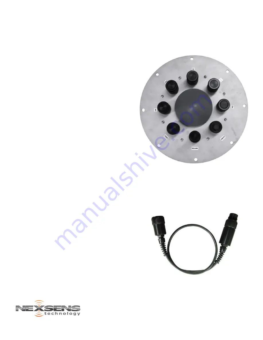
NexSens iSIC-CB Data Well Lid
For systems using NexSens electronics for data
acquisition and telemetry, the iSIC data logger is
housed in an iSIC-CB enclosure that provides a
watertight seal over the data well. The bottom of
the iSIC-CB has a power plug that connects to a
CB-A09-3/4 battery/solar regulator assembly.
The top of the iSIC-CB enclosure has a series of
UW ports for connection of solar panels, sensors,
communication devices, and external power
supplies to the iSIC.
The available ports and functions are:
-
(5)
SENSOR
(
P0/P1/P2
): NexSens sensorBUS
architecture includes wiring for SDI-12, RS-
232 and RS-485 devices. For compatibility,
sensors must have a factory-installed UW
plug connector. The sensor ports are wired as
follows:
(2)
P0
: 12V full power, shared RS-232 port.
(2)
P1
: 12V switch power, shared RS-232
port.
(1)
P2
: 12V switch power, unique RS-232
port.
-
(1)
COM
: Communications port for iSIC data
logger configuration and data acquisition
through
UW-USB-232P-NP
cable or
RTU-R/C/I
radio, cellular, or Iridium satellite telemetry
module.
-
(1)
SOLAR
: 6-pin input for solar panel to
apply system power and charge internal
battery. Solar cable or a specialized UW plug
with jumper (P/N
UW-JUMPER
) must be
connected to SOLAR port to power the iSIC.
-
(1)
VENT
: Gortex vent for relief of outgassing
pressure during recharge of batteries located
in the data well. In heavy wave conditions,
this vent can be plumbed with tubing to the
top of the tower.
The sharing of RS-232 ports on P0 and P1 means
that only one non-addressable device can be
connected at a time. For example, two devices
with RS-232 NMEA0183 output will interfere with
each other if both are connected to P0. RS-485
and SDI-12 ports are shared throughout the bus.
Figure 7:
iSIC-CB Enclosure
Devices with analog outputs (e.g. 4-20 mA, 0-2.5
VDC) may be connected to the iSIC-CB through a
mV-RS485
adapter, which converts the analog
signal to RS-485 Modbus. The
mV-RS485
adapter
must be programmed for the specific sensor
connected. See the instructions provided with the
adapter for more information.
Figure 8:
mV-RS485 Adapter


