FORM NO. L-20341-E-0208
ALIGNMENT (SEE FIGuRE 2)
1. The Transmitter must be the upper unit with
the Receiver mounted below when used with a
horizontal web run.
2. The angle of inclination to the web must be 45° + 5
o
.
3. The Transmitter to Receiver gap must be
2.36 + 0.20 in. [60 + 5 mm].
4. The lateral displacement must be within 0.20 In.
[5 mm].
5. The angular displacement must be 3
o
.
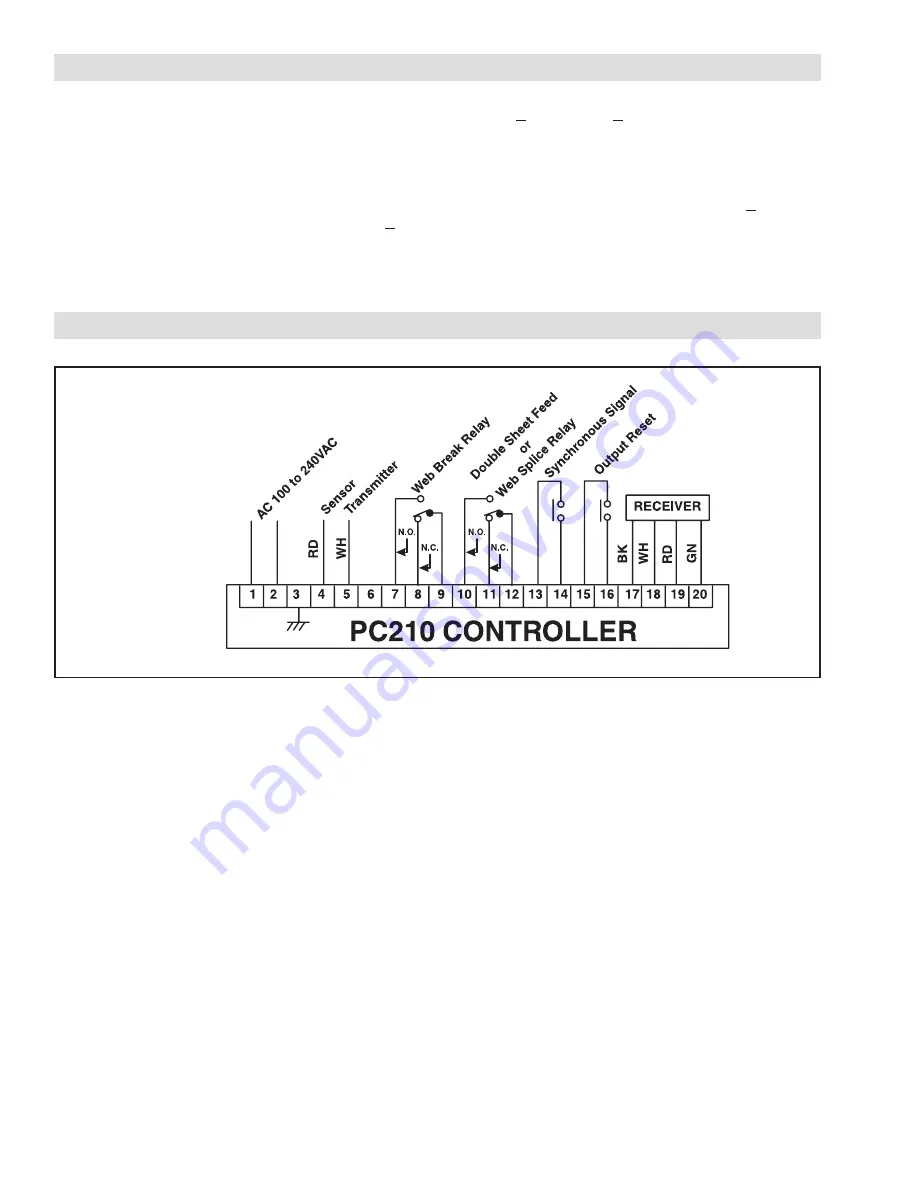
FIGuRE 3
1. Provide AC Power 100, 110, 120, 200, 220,
240VAC, 50 or 60 Hz at Terminals 1 and 2.
Connect the ground wire to Terminal 3 (See Figure
3).
2. Connect the Sensor Transmitter 16 ft. [5 m] cable to
Terminals 4 and 5 (See Figure 3).
NOTE: Do not extend this cable length.
3. Terminals 7, 8, and 9 provide the Web Break Relay
contact signal. Wire as appropriate for Normally
Open (N.O.) or Normally Closed (N.C.) logic (See
Figure 3).
4. Terminals 10, 11, and 12 provide the double sheet-
feed (two sheets stacked on top of each other)
contact signal for sheet-fed machines or the splice
contact signal for web-fed machines. Make electrical
connections as appropriate for N.O. or N.C. logic
(See Figure 3).
5. A relay may be connected to Terminals 13 and 14
to prevent triggering of either the Web Break or
Double Sheet Feed/Web Splice condition. The relay
must be a normally open type which closes when
triggering is to be prevented.
This Lock Out Relay is normally used to prevent
false triggering when the web or sheets stop moving
as the machine is stopped. As the web or sheets
stop moving they often change position (sag, relax
tension, etc.) which causes false triggering.
6. A remote button can be used to reset the system
after a double feed or splice signal, when the
machine is in manual reset mode. If this option is
used, a customer supplied N.O. momentary contact
remote Output Reset switch must be connected to
Terminals 15 and 16 (See Figure 3).
7. Connect the Sensor Receiver 16 ft. [5 m] cable to
Terminals 17, 18, 19, and 20 (See Figure 3).
NOTE: Do not extend this cable length.
INSTALLATION
(continued...)
ELECTRICAL CONNECTIONS


