Copyright © 2013 NEXCOM International Co., Ltd. All Rights Reserved.
5
NCr-301-VHR User Manual
Chapter 1: Product Introduction
Cable Installation
q
w
r
e
PHONE JACK
RJ45
y
t
u
i
q
w
r
e
PHONE JACK
RJ45
y
t
u
i
q
w
r
e
PHONE JACK
RJ45
y
t
u
i
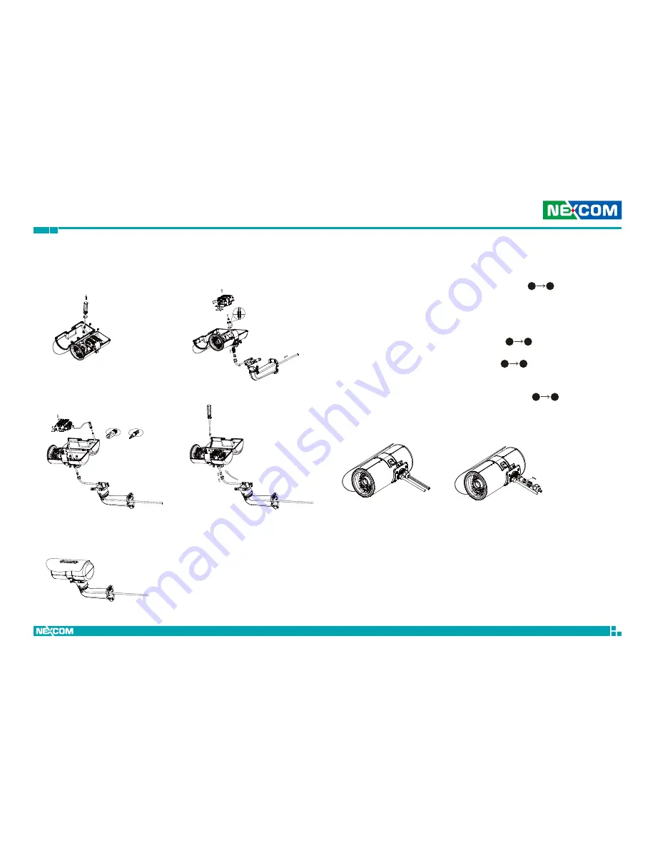
Cable Installation Steps:
1. Using a screwdriver, loosen the three mounting screws that hold the wall
mount bracket, then take out the MB module (
).
2. Run the cable inside the wall mount bracket and out through the cable
opening at the front, then slide the seal nut, tightening collar and main
body of the waterproof connector onto the cable. Now run the cable
through the opening at the bottom of the camera’s body, and place the
gasket and screw nut through the cable (
).
3. Insert the RJ45 connector onto the end of the cable, and plug it into the
corresponding port on the MB module (
).
4. Place the MB module back to its original position and secure it with
screws, then fasten the tightening collar and seal nut.
5. Install the camera onto the wall mount bracket (
).
1
3
5
7
8
6
4
2
u
i
Cable Wiring Description
1. The camera features two waterproof connectors, the left one in the
diagram is for PoE connection, while the right one is for line in, line out,
DC 12V/AC 24V and DI/O connections.
2. The right one features four wire holes. Please cover unused holes with
sealing plugs to prevent water from entering.
3. Applicable cable diameter:
▪
Ø 2.5~1.8mm (Right)
▪
Ø 6.9~4.7mm (Left)
Line Out
Line in
DC12V/AC24V
DI/DO
Ethernet/PoE


