


Fire Bird V ATMEGA2560 Hardware Manual
3.10 Sharp IR range sensors
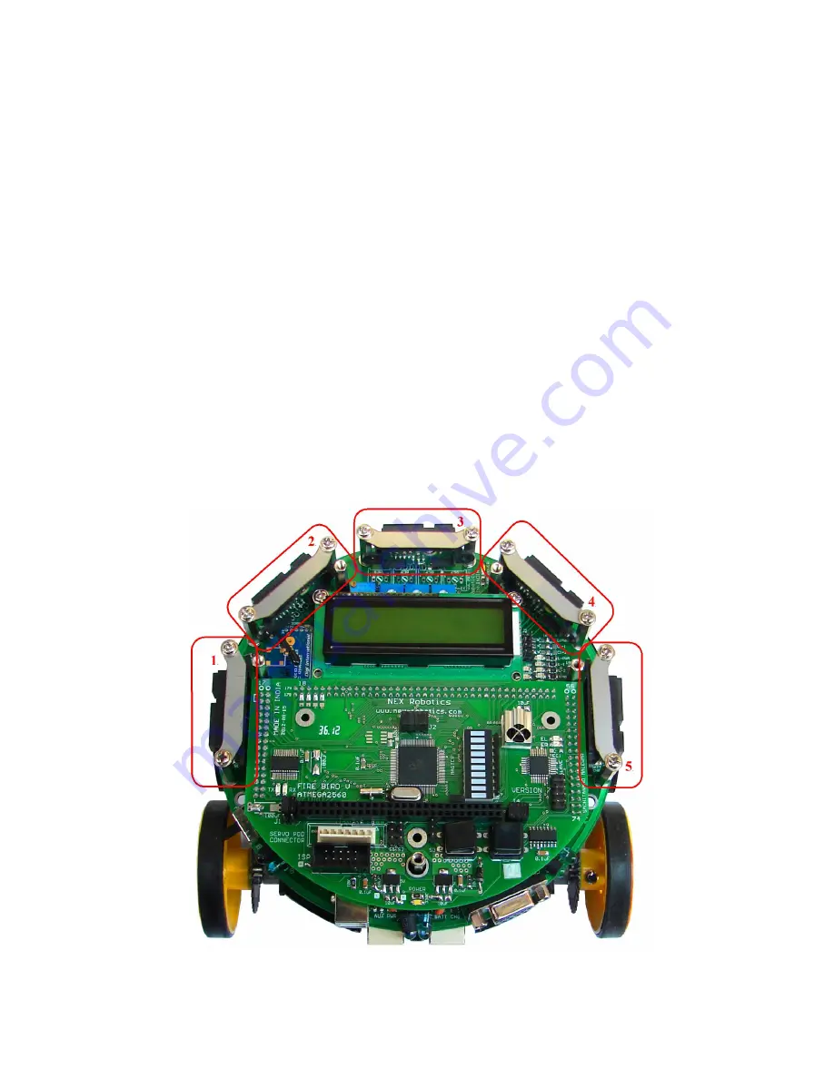
For accurate distance measurement, robot uses Sharp IR range sensors. Robot can be fitted with
five IR range sensors as shown in figure 3.29. Sharp IR range sensors consists of IR LED and
linear CCD array, both encapsulated in the housing with precision lens assembly mounted in
front of them. IR LED with the help of the leans transmits a narrow IR beam. When light hits the
obstacle and reflects back to the linear CCD array, depending on the distance from the obstacle,
angle of the reflected light varies. This angle is measured using the CCD array to estimate
distance from the obstacle. It gives same response to different colored objects as measured
distance is function of the angle of reflection and not on the reflected light intensity.
Figure 3.30 shows the internals of the sensor. Figure 3.31 explains how change in the distance
from the obstacle can be measured by measuring angle of reflection of the reflected light beam
from the obstacle. Since sensor measurement is based on triangulation and not on intensity of the
reflected light, it is immune to disturbance caused by ambient light.
Sensor gives out analog voltage corresponding to angle of reflection. Relationship between the
angle of reflection and output voltage is not linear because of trigonometry involved. These
sensors have blind spot in the range of 0mm to some specific distance depending on the type of
the sensor. In the blind spot region sensor gives incorrect readings. Table 3.9 gives information
about sensing range and the blind spot distance for the particular sensor.
Figure 3.29: Sharp Sensors mounted on Fire Bird V
© NEX Robotics Pvt. Ltd. and ERTS Lab, CSE, IIT Bombay, INDIA 40


