


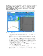


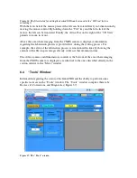


Z-Correction refers to modification of the “Z” component of fabrication-coordinates in
order to compensate for an actual-surface which is not parallel to the fabrication-surface
(Figure 39). For instance, the top surface of a microscope slide, placed under the
objective, may be in focus at (X,Y )= (0,0), but become out-of-focus if moved to (X,Y) =
(10000,10000) um. This would imply that the surface of the slide – the “actual-surface”
– deviates from the “fabrication-surface” – the (theoretical) plane traced by the focal-
point of objective. Z-Correction assumes that both the actual-surface and fabrication-
surface are approximately planer; a delta-Z can be calculated for any (X,Y) position, and,
this delta-Z is used to “correct” the coordinates used during fabrication. Z-Correction is
enabled by supplying the three points, P0, P1 and P2.
Coordinates for these three points can be entered directly on the “Z-Correction” window,
or replaced, individually, by pressing the P0, P1 or P2 button on the “MOVE” window.
Z-Correction is accomplished by determining three, non-origin points lying on the part’s
surface, and copying those points to \TOOLS\Z-Correction. For convenience, current
position can be copied to P0 or P1 or P2 by pressing a button on the “MOVE” window.
Z-Correction is only applied to Z-coordinates when “Run” is executed. Z-Correction is
disabled if P0 or P1 or P2 is (0,0,0).
Figure 39. The “Z-Correction” window.
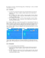
6.4.2 “Diagnostics”
•
uFAB Files Path
: it indicates the last file in use.
•
Quit
: the software is turned off.
•
Get Absolute Offset
: it returns the absolute position (in mm) of the stages.
•
Zero Absolute Offsets
: it sets actual positions to origin (0,0,0).
•
Re-Initialize XYZ Axes
: it initializes the stage group used in the
femto
FBG.
•
Open Shutter-server STATUS
: it indicates the status of the shuttering system.