


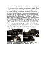


aperture of the OL and also to verify that the beam is not clipped and/or diffracted. The
beam must show a clean and round pattern as shown in Figure 11(a). Furthermore, the
same method is used to check the laser beam after the OL in order to ensure that the laser
beam goes straight through it. Because of the large OL numerical aperture, we
recommend checking this while the beam is defocusing such as in Figure 11(b).
Figure 11. The shape and size of the laser beam is visually inspected with the aid of a white piece of
paper before (a) and after (b) the OL.
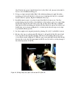
In the vertical compartment of the
femto
FBG, L
1
and L
2
are used to expand the laser
beam diameter so to match or overfill the diameter of the OL back aperture. It is
important to perform this task in order to take full advantage of the OL numerical
aperture and hence achieve the smallest beam diameter at the OL focal plane. To test the
size and collimation of the laser beam after L
1
and L
2
, a temporary mirror in a 45° mount
is used before the OL to project the laser beam at a distance.
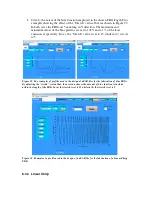
Figure 12. An auxiliary mirror mounted at 45° is sued to check the laser beam collimation. The 45°
mirror is positioned just before the OL entrance (a). With the aid of a piece of paper, the laser beam
diameter is checked in two positions, one close and one far to the 45° mirror (b).
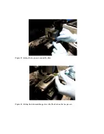
Figure 12 (a) shows where to rest the 45° mirror in the metallic bracket that holds the
piezo focusing stage and the OL; ensures that the laser beam does not clip the 45° mirror.
Figure 12 (b) illustrates the locations where to check the laser beam diameter. If L
1
and