


•
Power
: the reading from the
femto
FBG internal power meter is displayed here. A
pull down menu on its right permits to change the scale of the measurement from
W to
µ
W. The laser average power displayed here is not the laser average power
used at the sample. It is the fraction (
∼
4%) of the laser average power as
measured in the vertical section of the
femto
FBG.
•
Profile Type
: it enables the user to choose amongst a variety of FBGs patterns. A
pull down menu is shown when the white part is left clicked.
•
Length
: it defines the total length (in mm) of the FBG to be manufactured.
•
Travel Axis
: it defines which of the two linear stages will be moved while writing
the FBG. Because of the stages’ assembly orientation, the stage that moves in the
same direction of the fiber main axis is the Y one.
•
Positive?
: By using this toggle, the customer can change the direction of the FBG
writing along the determined travel axis. For example if the travel axis is the Y
one, then when “positive” the writing occurs towards positive values of the y axis,
and when “negative” the writing occurs towards negative values of the y axis.
•
Velocity
: set the velocity (
µ
m/s) of the travel axis chosen to be used while writing
a FBG.
•
Save
: it enables to save the prepared file as a uFAB fife in the chosen directory.
•
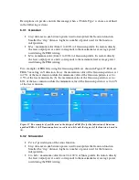
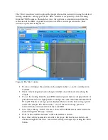
FBG Autoscale
: Before saving a specific pattern, the “Design” window displays a
graphical representation of such pattern. The Autoscale scale function act on this
graphical representation by fitting the data within proper values.
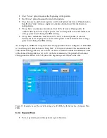
Figure 26. The “Design” window.