background image

CONEX-CC 

Controller GUI Manual 

4.0


User Interface 

4.1


Configuration 


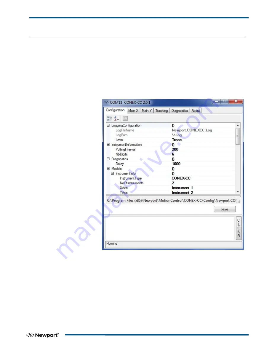
The Configuration tab allows the user to view and / or change information related to 

the logging configuration and the instrument settings. Read only values are displayed 

for the log file name and the log file path. The logging level may be changed to any of 

the settings in the drop-down list on the right hand side. Trace is the most detailed of 

the settings and when this setting is selected the Controller GUI logs everything. 

Critical Error is the least detailed of the settings and when this setting is selected the 

Controller GUI will only log errors that are defined to be critical.  


The polling interval defines the number of milliseconds between each time the 

Controller GUI polls the CONEX-CC for the latest information. The user may change 

the polling interval by entering a value. Diagnostics Delay defines the time delay in 

milliseconds between each command sent from a text file.  
InstrumentType and NoOfInstruments display the name and number of connected 

instruments.  
The 

Save

 button allows to save the current settings to the configuration file. 


EDH0277En1041 — 10/17


Содержание CONEX-CC

Страница 1: ...CONEX CC Single Axis DC Motion with Controller Driver Controller GUI Manual V2 0 x...

Страница 2: ...uctions No part of this document may be reproduced or copied without the prior written approval of Newport Corporation This document is provided for information only and product specifications are sub...

Страница 3: ...Controller State Diagram 2 2 0 Installation 3 2 1 Install CONEX CC Graphical User Interface 3 2 2 Launch GUI 3 3 0 Getting Started 4 3 1 Discover Instruments 4 4 0 User Interface 5 4 1 Configuration...

Страница 4: ...CONEX CC Controller GUI Manual EDH0277En1041 10 17 iv...

Страница 5: ...r interface GUI 1 2 Overview The CONEX CC Controller GUI is a graphical user interface that allows the user to interact with the CONEX CC controller that is connected to stages with DC motors and enco...

Страница 6: ...ion 2 0 0 Controller s LED display NOT REFERENCED If everything is OK then SOLID ORANGE NOT REFERENCED If hardware faults or wrong parameters then SOLID RED NOT REFERENCED If end of runs then SLOW BLI...

Страница 7: ...n folder selection By default it is showing C Click on Next Ready to install window opens up Click Install Then installation starts wait for completion Click on Finish to finalize the installation 32...

Страница 8: ...ill appear This window allows the user to select a com port where the desired instrument is connected NOTE When more than one CONEX CC instrument is connected this window allows the user to switch the...

Страница 9: ...er GUI logs everything Critical Error is the least detailed of the settings and when this setting is selected the Controller GUI will only log errors that are defined to be critical The polling interv...

Страница 10: ...tions is a list of memorized positions The format is Name of positions 1 X position 1 Y position 2 Models InstrumentInfo XAxis XAxis defines the instrument for X axis None no instrument for X axis Ins...

Страница 11: ...t Middle Click SelectXaxis Select Unselect X axis MouseButton MouseEvent Left Click SelectYaxis Select Unselect Y axis MouseButton MouseEvent Right Click IncreaseSensibility Increase the zoom level of...

Страница 12: ...e different controller states refer to the controller state diagram in section 1 3 The second button Save Pos memorizes the current positions X and Y in the combo box As soon as a new position is memo...

Страница 13: ...and the velocity are displayed in a disabled text box Minimum end of run Maximum end of run and Velocity These ends of run and the velocity can be modified and saved with the Set button Memorised posi...

Страница 14: ...ouse hovers over the LED icon the controller state is displayed inside an information balloon Two text boxes display the current positions X and Y The combo box allows memorizing the positions with a...

Страница 15: ...hand and the CONEX CC goes to the TRACKING state Next each mouse move generates a displacement command The second click middle mouse button exits the tracking mode The wheel button increases or decrea...

Страница 16: ...commands and to view the history of commands that were sent and the responses that were received This list of commands and the syntax of each command can be found in the user s manual A file of comman...

Страница 17: ...e information about the Controller GUI and the connected instrument It displays the Controller GUI name version and copyright information It also displays the instrument model instrument key serial nu...

Страница 18: ...CONEX CC Controller GUI Manual EDH0277En1041 10 17 14...

Страница 19: ...____________________________________________________________________________________________________________ ___________________________________________________________________________________________...

Страница 20: ...mail tech newport com Service RMAs Returns Tel 800 222 6440 e mail service newport com Europe MICRO CONTROLE Spectra Physics S A S 9 rue du Bois Sauvage 91055 vry CEDEX France Sales Tel 33 0 1 60 91 6...

Отзывы: