


6
2.3
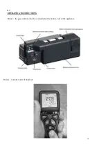
FLUE CONNECTION
The flue should be at least 3m high and at least 125 mm diameter (5”) at no point should there be any
negative or horizontal gradients in the flue pipe.
It is recommended that a minimum height of 600mm from the stove before any significant change of
direction of the flue.
2.4
VENTILATION
Ventilation should be in accordance with national regulations in the UK purpose provided ventilation
is not normally required BS5871 part 1 and in IE IS813 (IE only)
2.5
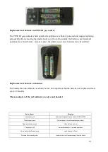
GAS CONNECTION
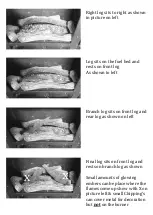
The gas connection can be made by removing the glass including the retaining frame and seal by
removing the bolts holding it in place once removed the 4 bolts holding the burner in place can be
removed and access to the gas inlet elbow can be gained, once the connection is made and
soundness verified the burner can be replaced ensuring correct position and the 4 bolts then
replaced.


