Newman FLAME VIEW ST1 Скачать руководство пользователя страница 12


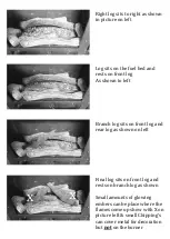
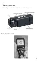
Hold the handset as shown, wrapping your 

hand around the handset touching both 

sides. In a second or less the green unlock 

light will illuminate

allowing the buttons 

to work when pushed

(NOTE: If the green light is not a constant 

green or not lit at all the buttons will not 

be operable). 


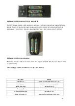
Press and hold in the power symbol 

button and release immediately when the 

word pilot comes on to the display at the 

bottom left as shown (about 1-2 seconds). 

The stove will light. 

(NOTE: Releasing too soon or too long 

after the pilot illumination, results in the 

Iire not lighting, this is for safety reasons). 


To adjust high and low whilst holding the handset and green light on press + & - 

to adjust preferred setting 

To Stop the stove, hold handset to unlock the buttons and then press the 

1

p

2

ower 

button. The flame stops almost immediately. 

Содержание FLAME VIEW ST1

Страница 1: ...arm Doublegate Lane Wickford Essex SS11 8UD FLAME VIEW ST1 GAS STOVE THIS APPLIANCE IS CATEGORY I2H FOR USE WITH NATURAL GAS AT A SUPPLY PRESSURE OF 20 mbar G B INSTALLATION SERVICING BOOK THIS MANUAL...

Страница 2: ...TABILITY 3 4 2 0 INSTALLATION 5 2 1 HEARTH 5 2 2 SITING 5 2 3 FLUE CONNECTION 5 2 4 VENTILATION 5 2 5 GAS CONNECTION 6 2 6 FUEL FITTING 7 8 2 7 OPERATING INSTRUCTIONS 9 10 11 12 2 8 SPILLAGE 13 2 9 CU...

Страница 3: ...a competent person installs all gas appliances i e a gas registered installer in accordance with the current edition of the gas safety installation and use regulations or the rules in force Failure to...

Страница 4: ...he inside of the chimney flue is in good condition along its length and check that there is no leakage of smoke through the structure of the chimney flue during and after the smoke pellet test 5 Using...

Страница 5: ...be fitted for protection of young children or elderly or infirm persons The door must be opened to remove the glass allow to cool before removing this as it will become very hot and is a working surfa...

Страница 6: ...dance with national regulations in the UK purpose provided ventilation is not normally required BS5871 part 1 and in IE IS813 IE only 2 5 GAS CONNECTION The gas connection can be made by removing the...

Страница 7: ...ut the type or number of logs Completely fill the burner with the mica supplied Ensure if any spills into pilot it is removed Do not use appliance without the mica in the burner Rear log sits as shown...

Страница 8: ...shown to left Branch log sits on front log and rear log as shown on left Final log sits on front log and Small amounts of glowing flames come up show with X on picture left small Chipping s can cover...

Страница 9: ...9 2 7 OPERATING INSTRUCTIONS Below the gas controls which are situated at the bottom left of the appliance Below remote control handset...

Страница 10: ...et The handset also has batteries as shown below It is important that the batteries are replaced at least every 12 months The meaning s of the red indicator on valve and handset Red indicator Meaning...

Страница 11: ...ote This button press must be done with 1 second of the red light coming on If not done quickly enough then the above must be repeated until done correctly When done correctly you will hear an audible...

Страница 12: ...ower symbol button and release immediately when the word pilot comes on to the display at the bottom left as shown about 1 2 seconds The stove will light NOTE Releasing too soon or too long after the...

Страница 13: ...uel pieces are added and only authorised spares are used 3 0 SERVICING INSTRUCTIONS The stove is fitted with a spillage monitoring system consisting of a thermal switch this system is not adjustable a...

Страница 14: ...aling and contact with skin or eyes Use disposable gloves facemasks and eye protection After handling wash hands and other exposed parts If a vacuum is used for cleaning any ceramic fuel bed parts inc...

Отзывы: