


38
OPEN CONTROL BOX
Begin by removing the 4 Phillips head screws
hold ing the Control Box together. These are acces-
sed by turning the Control Box upside down. Once
the 4 screws are removed, you can lift the bottom
cover off, exposing the PCB inside.
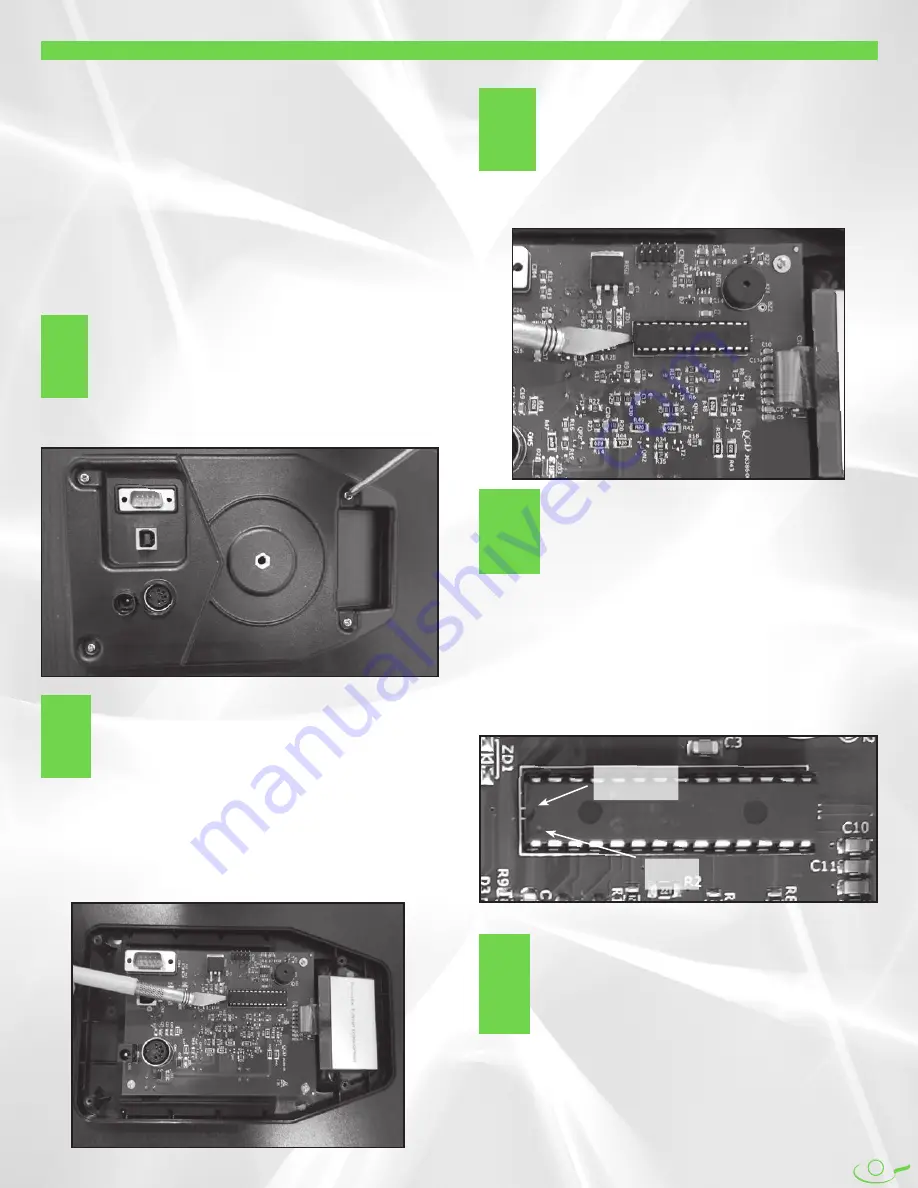
PRY UP CHIP
The chip sits in a raised black chip holder that is
close to and parallel with the LCD Screen at one
end of the PCB. Remove the chip by prying it out
of the chip holder. Special tools are available to do
this and should be used if you have them
available, but they aren't required. You can also use a tiny
flat head screwdriver or an Xacto-type knife. Slide your
tool be tween the chip and the chip holder while being
careful not to bend or harm the pins of the chip. Gently pry
upwards to lift the chip slightly out of the connector.
REMOVE OLD CHIP
Once you have lifted one side of the chip up
slightly, switch to the other end of the chip and
do the same thing. Work back and forth between
the two ends, prying the chip up a little more
each time until the chip lifts away from the chip
holder. Set the old chip aside.
REASSEMBLE CONTROL BOX
Reattach the Bottom Control Box Housing with
the four screws removed in Step 1. Plug the
Control Box into power. The initial boot-up screen
will show the new firmware version briefly. Please
note that the 64 factory drills are stored on this
chip. Any custom drills you have stored in positions 33–64
will not be there anymore. Reinstall them if necessary. Also
all Calibration settings are restored to their factory default
status, so you will need to recalibrate any of these settings
that you have changed. We recommend recording all your
calibration settings on the back cover of this manual.
REPLACING THE MICROPROCESSOR CHIP
1
2
3
5
Most of the unique features and controls made possible by
the digital design of the Control Box are contained in the
programming that is burned into the microprocessor. This
programming is referred to as the firmware. The PCB
(Printed Circuit Board) is designed so that the microproces-
sor can be changed out easily when the firmware is updat-
ed to add features or provide improved perfor mance.
Newgy will periodically update the firmware and let own-
ers of our robots know that a new firmware version is
available. The firmware will be provided on a new chip
that can easily be swapped out with the existing one. This
section will detail how to replace the microprocessor.
INSTALL NEW CHIP
Install the new chip but be careful to properly
orient the chip and to not bend the pins. Locate
the small semi-circular notch at one end of the
new chip. This marks the left end of the chip.
Imme diately below that notch is a small dot-shaped
depression. The dot marks pin 1. Install the chip so that pin
1 goes into the bottom leftmost slot of the chip holder. It
may be neces sary to gently bend the pins for all the pins to
line up properly with all of the slots. Then gently and
slowly press the chip into the holder until you are sure that
all the pins are going into their associated slots. Then press
firmly to seat the pin fully into the holder.
4
#1 Pin
Mark
Semi-circular
Notch


